

人道真传--计网实验流程
计算机网络实验
实验一 网络命令的使用
ping命令检测网络故障的次序
打开win + r 输入cmd 回车确定
在命令行输入
ping 127.0.0.1
结果如下
正在 Ping 127.0.0.1 具有 32 字节的数据:
来自 127.0.0.1 的回复: 字节=32 时间<1ms TTL=128
来自 127.0.0.1 的回复: 字节=32 时间<1ms TTL=128
来自 127.0.0.1 的回复: 字节=32 时间<1ms TTL=128
来自 127.0.0.1 的回复: 字节=32 时间<1ms TTL=128

127.0.0.1 的 Ping 统计信息:
    数据包: 已发送 = 4,已接收 = 4,丢失 = 0 (0% 丢失),
往返行程的估计时间(以毫秒为单位):
    最短 = 0ms,最长 = 0ms,平均 = 0ms
ping 查看本机IP地址
在命令行输入
ping 192.168.1.101
结果如下
正在 Ping 192.168.1.101 具有 32 字节的数据:
来自 192.168.1.101 的回复: 字节=32 时间<1ms TTL=128
来自 192.168.1.101 的回复: 字节=32 时间<1ms TTL=128
来自 192.168.1.101 的回复: 字节=32 时间<1ms TTL=128
来自 192.168.1.101 的回复: 字节=32 时间<1ms TTL=128

192.168.1.101 的 Ping 统计信息:
    数据包: 已发送 = 4,已接收 = 4,丢失 = 0 (0% 丢失),
往返行程的估计时间(以毫秒为单位):
    最短 = 0ms,最长 = 0ms,平均 = 0ms
ping查看本计算机是否与其他计算机通信
在命令行输入其他计算机的IP地址
ping 1.14.44.81
来自 1.14.44.81 的回复: 字节=32 时间=68ms TTL=115
来自 1.14.44.81 的回复: 字节=32 时间=9ms TTL=114
来自 1.14.44.81 的回复: 字节=32 时间=11ms TTL=114
来自 1.14.44.81 的回复: 字节=32 时间=55ms TTL=114

1.14.44.81 的 Ping 统计信息:
    数据包: 已发送 = 4,已接收 = 4,丢失 = 0 (0% 丢失),
往返行程的估计时间(以毫秒为单位):
    最短 = 9ms,最长 = 68ms,平均 = 35ms
ping查看域名判断是否通外网
命令行输入
ping dyfl.top
可以看到可以ping通
正在 Ping dyfl.top [159.75.154.230] 具有 32 字节的数据:
来自 159.75.154.230 的回复: 字节=32 时间=39ms TTL=49
来自 159.75.154.230 的回复: 字节=32 时间=105ms TTL=48
来自 159.75.154.230 的回复: 字节=32 时间=47ms TTL=48
来自 159.75.154.230 的回复: 字节=32 时间=42ms TTL=48

159.75.154.230 的 Ping 统计信息:
    数据包: 已发送 = 4,已接收 = 4,丢失 = 0 (0% 丢失),
往返行程的估计时间(以毫秒为单位):
    最短 = 39ms,最长 = 105ms,平均 = 58ms
ipconfig
使用ipconfig/all命令
查看本机的IP地址、子网掩码、网关、DNS、MAC地址.
命令行输入
ipconfig/all
Windows IP 配置

   主机名  . . . . . . . . . . . . . : LAPTOP-JN22HMHF
   主 DNS 后缀 . . . . . . . . . . . :
   节点类型  . . . . . . . . . . . . : 混合
   IP 路由已启用 . . . . . . . . . . : 否
   WINS 代理已启用 . . . . . . . . . : 否

以太网适配器 以太网:

   媒体状态  . . . . . . . . . . . . : 媒体已断开连接
   连接特定的 DNS 后缀 . . . . . . . :
   描述. . . . . . . . . . . . . . . : Realtek PCIe GbE Family Controller
   物理地址. . . . . . . . . . . . . : 50-EB-F6-4C-B6-7C
   DHCP 已启用 . . . . . . . . . . . : 是
   自动配置已启用. . . . . . . . . . : 是

未知适配器 本地连接:

   媒体状态  . . . . . . . . . . . . : 媒体已断开连接
   连接特定的 DNS 后缀 . . . . . . . :
   描述. . . . . . . . . . . . . . . : QMTAP Adapter V9
   物理地址. . . . . . . . . . . . . : 00-FF-D4-E1-80-23
   DHCP 已启用 . . . . . . . . . . . : 否
   自动配置已启用. . . . . . . . . . : 是

无线局域网适配器 本地连接* 9:

   媒体状态  . . . . . . . . . . . . : 媒体已断开连接
   连接特定的 DNS 后缀 . . . . . . . :
   描述. . . . . . . . . . . . . . . : Microsoft Wi-Fi Direct Virtual Adapter
   物理地址. . . . . . . . . . . . . : 36-6F-24-9A-D9-A5
   DHCP 已启用 . . . . . . . . . . . : 是
   自动配置已启用. . . . . . . . . . : 是

无线局域网适配器 本地连接* 13:

   连接特定的 DNS 后缀 . . . . . . . :
   描述. . . . . . . . . . . . . . . : Microsoft Wi-Fi Direct Virtual Adapter #5
   物理地址. . . . . . . . . . . . . : 36-6F-24-9A-D9-B5
   DHCP 已启用 . . . . . . . . . . . : 否
   自动配置已启用. . . . . . . . . . : 是
   本地链接 IPv6 地址. . . . . . . . : fe80::9bb:e3a9:2b4:82c8%7(首选)
   自动配置 IPv4 地址  . . . . . . . : 169.254.125.14(首选)
   子网掩码  . . . . . . . . . . . . : 255.255.0.0
   默认网关. . . . . . . . . . . . . :
   DHCPv6 IAID . . . . . . . . . . . : 825650980
   DHCPv6 客户端 DUID  . . . . . . . : 00-01-00-01-29-5B-DA-12-50-EB-F6-4C-B6-7C
   DNS 服务器  . . . . . . . . . . . : fec0:0:0:ffff::1%1
                                       fec0:0:0:ffff::2%1
                                       fec0:0:0:ffff::3%1
   TCPIP 上的 NetBIOS  . . . . . . . : 已启用

无线局域网适配器 WLAN:

   连接特定的 DNS 后缀 . . . . . . . :
   描述. . . . . . . . . . . . . . . : MediaTek Wi-Fi 6 MT7921 Wireless LAN Card
   物理地址. . . . . . . . . . . . . : 34-6F-24-9A-D9-E5
   DHCP 已启用 . . . . . . . . . . . : 是
   自动配置已启用. . . . . . . . . . : 是
   本地链接 IPv6 地址. . . . . . . . : fe80::67c8:47e3:776:eaae%3(首选)
   IPv4 地址 . . . . . . . . . . . . : 192.168.1.101(首选)
   子网掩码  . . . . . . . . . . . . : 255.255.255.0
   获得租约的时间  . . . . . . . . . : 2024年11月29日 19:12:02
   租约过期的时间  . . . . . . . . . : 2024年11月30日 0:12:32
   默认网关. . . . . . . . . . . . . : 192.168.1.1
   DHCP 服务器 . . . . . . . . . . . : 192.168.1.1
   DHCPv6 IAID . . . . . . . . . . . : 255094564
   DHCPv6 客户端 DUID  . . . . . . . : 00-01-00-01-29-5B-DA-12-50-EB-F6-4C-B6-7C
   DNS 服务器  . . . . . . . . . . . : 192.168.16.1
                                       8.8.8.8
   TCPIP 上的 NetBIOS  . . . . . . . : 已启用

以太网适配器 蓝牙网络连接:

   媒体状态  . . . . . . . . . . . . : 媒体已断开连接
   连接特定的 DNS 后缀 . . . . . . . :
   描述. . . . . . . . . . . . . . . : Bluetooth Device (Personal Area Network)
   物理地址. . . . . . . . . . . . . : 34-6F-24-9A-D9-E4
   DHCP 已启用 . . . . . . . . . . . : 是
   自动配置已启用. . . . . . . . . . : 是
查看DHCP协议获取的的
命令行输入
ipconfig/renew
结果如下
不能在 本地连接 上执行任何操作,它已断开媒体连接。
不能在 本地连接* 9 上执行任何操作,它已断开媒体连接。
不能在 蓝牙网络连接 上执行任何操作,它已断开媒体连接。

以太网适配器 以太网:

   媒体状态  . . . . . . . . . . . . : 媒体已断开连接
   连接特定的 DNS 后缀 . . . . . . . :

未知适配器 本地连接:

   媒体状态  . . . . . . . . . . . . : 媒体已断开连接
   连接特定的 DNS 后缀 . . . . . . . :

无线局域网适配器 本地连接* 9:

   媒体状态  . . . . . . . . . . . . : 媒体已断开连接
   连接特定的 DNS 后缀 . . . . . . . :

无线局域网适配器 本地连接* 13:

   连接特定的 DNS 后缀 . . . . . . . :
   本地链接 IPv6 地址. . . . . . . . : fe80::9bb:e3a9:2b4:82c8%7
   自动配置 IPv4 地址  . . . . . . . : 169.254.125.14
   子网掩码  . . . . . . . . . . . . : 255.255.0.0
   默认网关. . . . . . . . . . . . . :

无线局域网适配器 WLAN:

   连接特定的 DNS 后缀 . . . . . . . :
   本地链接 IPv6 地址. . . . . . . . : fe80::67c8:47e3:776:eaae%3
   IPv4 地址 . . . . . . . . . . . . : 192.168.1.101
   子网掩码  . . . . . . . . . . . . : 255.255.255.0
   默认网关. . . . . . . . . . . . . : 192.168.1.1

以太网适配器 蓝牙网络连接:

   媒体状态  . . . . . . . . . . . . : 媒体已断开连接
   连接特定的 DNS 后缀 . . . . . . . :
ARP命令
在命令行里面输入
arp —a
查看高速缓存中的所有项目,如下
  Internet 地址         物理地址              类型
  192.168.1.1           4c-77-66-c0-62-cb     动态
  192.168.1.100         2e-1e-c3-d4-55-7e     动态
  192.168.1.255         ff-ff-ff-ff-ff-ff     静态
  224.0.0.22            01-00-5e-00-00-16     静态
  224.0.0.251           01-00-5e-00-00-fb     静态
  224.0.0.252           01-00-5e-00-00-fc     静态
  239.255.255.250       01-00-5e-7f-ff-fa     静态
  255.255.255.255       ff-ff-ff-ff-ff-ff     静态

接口: 169.254.125.14 --- 0x7
  Internet 地址         物理地址              类型
  169.254.255.255       ff-ff-ff-ff-ff-ff     静态
  224.0.0.22            01-00-5e-00-00-16     静态
  224.0.0.251           01-00-5e-00-00-fb     静态
  239.255.255.250       01-00-5e-7f-ff-fa     静态
arp —d 删除指定的IP地址
我没有IP可以删除
就不演示了
Tracert命令
命令行输入
Tracert 1.14.44.81
结果如下
  1    29 ms     3 ms    <1 毫秒 192.168.1.1
  2     4 ms     8 ms    <1 毫秒 myblink.cn [192.168.16.1]
  3    32 ms     1 ms     4 ms  10.40.0.1
  4     8 ms    83 ms     4 ms  10.100.1.21
  5     3 ms     8 ms     2 ms  171.211.123.1
  6     9 ms     8 ms     2 ms  217.151.157.61.dial.dy.sc.dynamic.163data.com.cn [61.157.151.217]
  7     *        *        *     请求超时。
  8    54 ms     *       64 ms  182.140.220.194
  9     *        *        *     请求超时。
 10     *        *        *     请求超时。
 11     *        *        *     请求超时。
 12    11 ms    13 ms     9 ms  1.14.44.81

跟踪完成。
Tracert —d 查看某个服务器的路劲信息
命令行输入
Travert dyfl.top
结果如下
通过最多 30 个跃点跟踪
到 dyfl.top [159.75.154.230] 的路由:

  1    21 ms    <1 毫秒   <1 毫秒 192.168.1.1
  2     3 ms     2 ms     1 ms  192.168.16.1
  3     2 ms     1 ms     1 ms  10.40.0.1
  4   348 ms     1 ms     1 ms  10.100.1.21
  5     3 ms     2 ms     2 ms  171.211.123.1
  6    37 ms     *       66 ms  61.157.150.241
  7     *        *        *     请求超时。
  8     *        *        *     请求超时。
  9     *       37 ms     *     219.128.214.2
 10     *        *        *     请求超时。
 11    45 ms    71 ms   243 ms  14.18.199.98
 12     *        *        *     请求超时。
 13     *        *        *     请求超时。
 14     *        *        *     请求超时。
 15     *        *        *     请求超时。
 16    38 ms    38 ms    48 ms  159.75.154.230

跟踪完成。
实验1完成
实验二 二层交换的的基本配置
实验二我们需要安装思科模拟器
我准备了6.2版本的 链接在下面
链接: https://pan.baidu.com/s/1XnPSaBrvfAqa3GLZrHLYWA?pwd=514e 提取码: 514e 复制这段内容后打开百度网盘手机App,操作更方便哦
Cisco Packet Tracer Student这个软件是纯英文的,不符合中国宝宝的体质
让我们来汉化它,在我准备的压缩包里面,有这样的一个插件chinese_v1.0.ptl 我们需要把这个文件放到安装路径下的languages文件夹里面
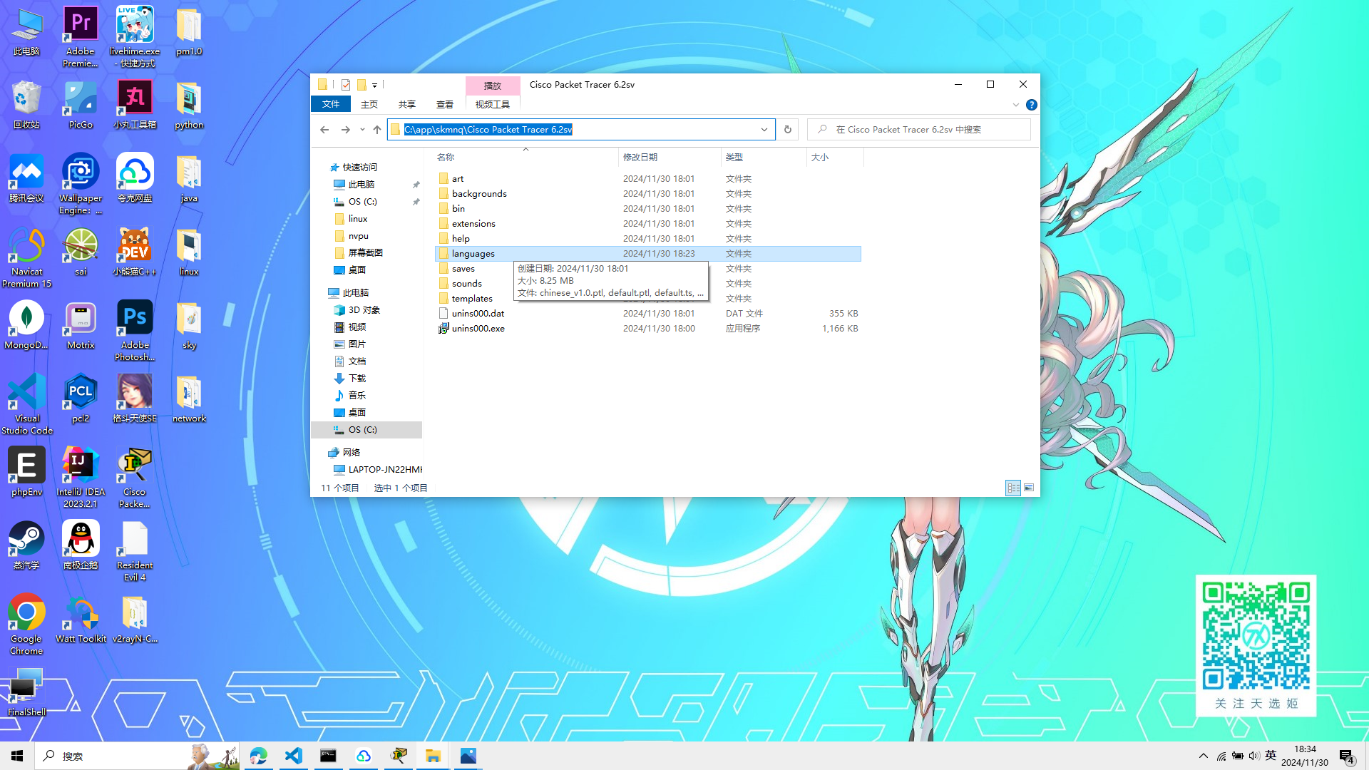
 然后进入Cisco Packet Tracer Student设置
选择菜单栏的Options
然后进入Cisco Packet Tracer Student设置
选择菜单栏的Options
 再选择第一个preferences
然后将启用端口标签打勾
再选择第一个preferences
然后将启用端口标签打勾
 再选中我们的插件,点击更改语言包,重新启动就是中文了
完成语言的设置后,就可以开始做实验了
再选中我们的插件,点击更改语言包,重新启动就是中文了
完成语言的设置后,就可以开始做实验了
Cisco Packet Tracer Student 启动!!!
交换机的配置模式
建立如图的交换机和PC机器,自动选择链接类型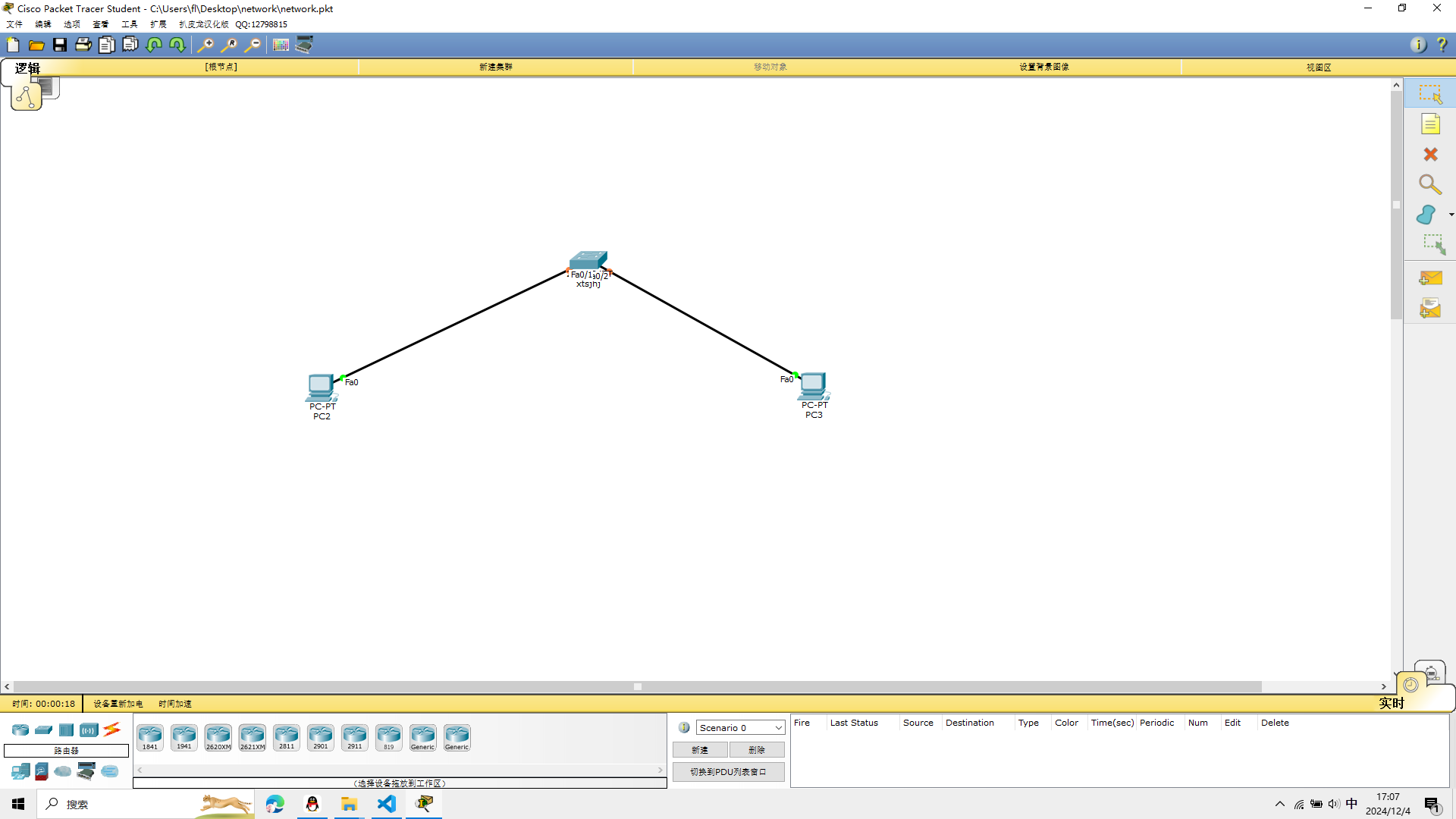
重命名
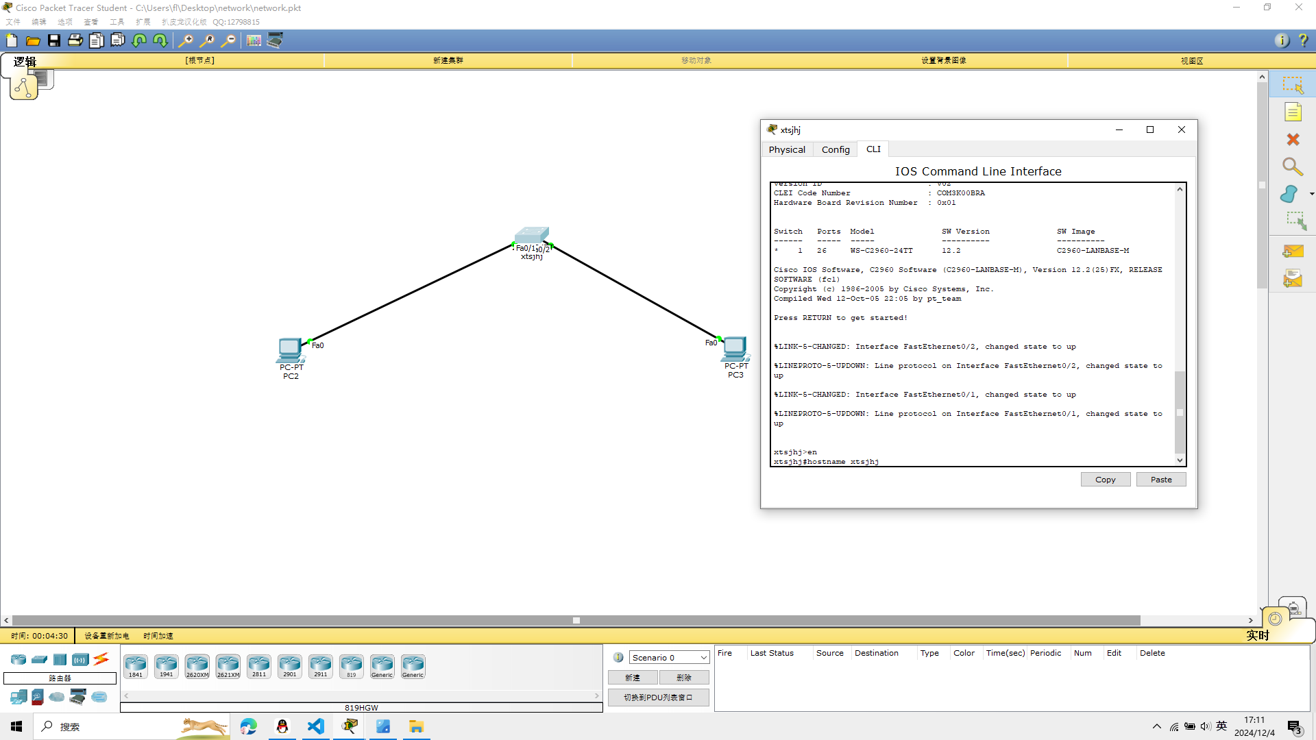
打开交换机终端,输入enable
进入特权模式,然后我们先给交换机改一个名字
enable
当终端出现#号就表示进入了特权模式
hostname xtsjhj
取一个名字
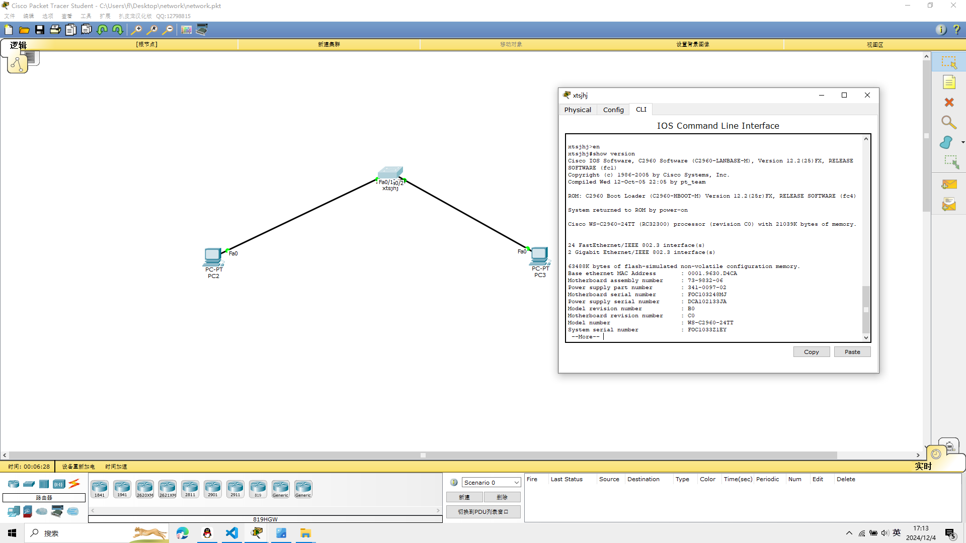
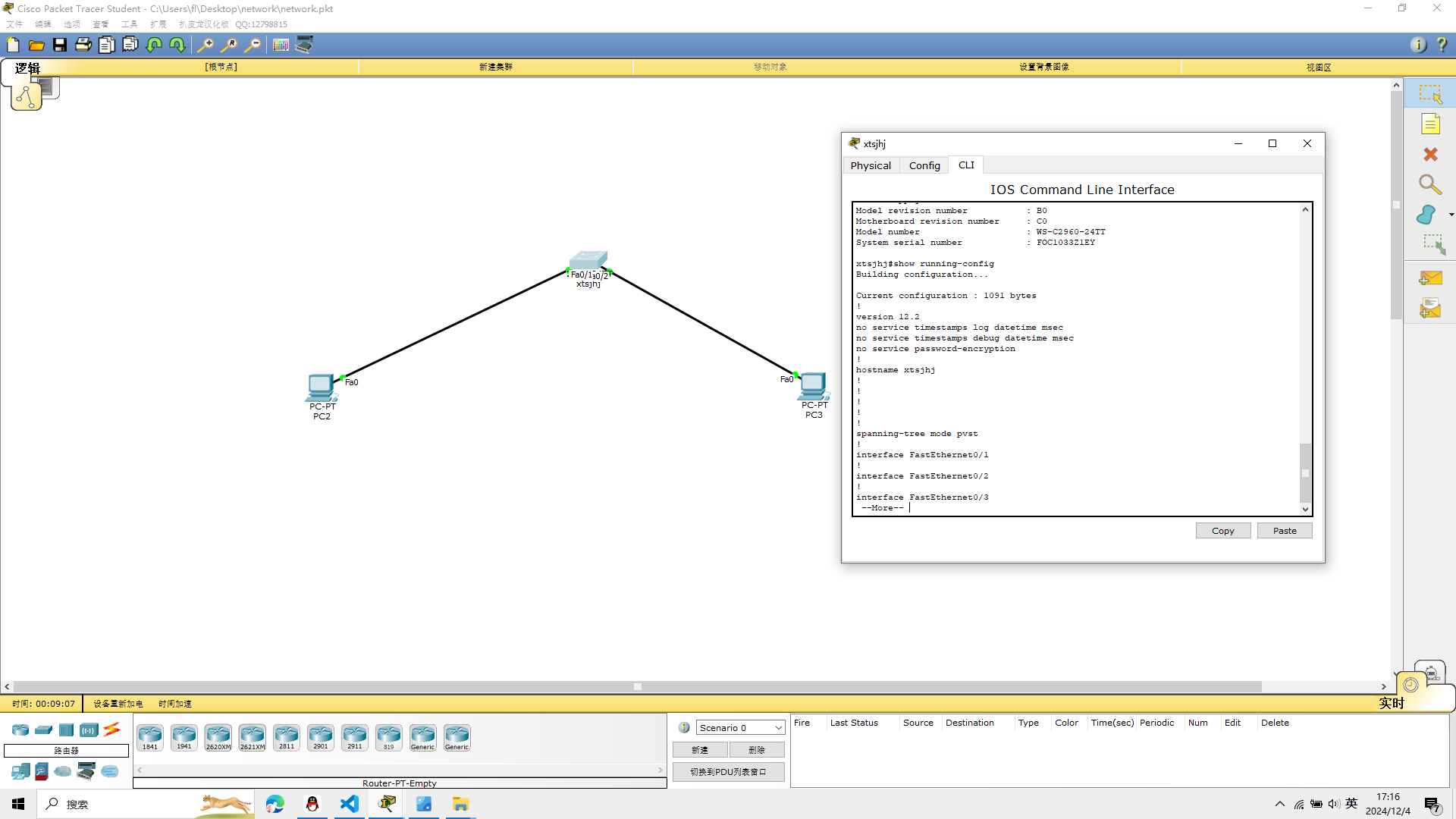
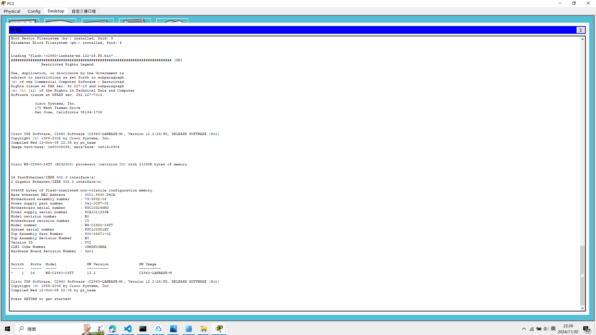
显示配置信息
在终端输入
show version
可以看到这个IOS的版本
查看交换机的配置信息
输入
show running-config
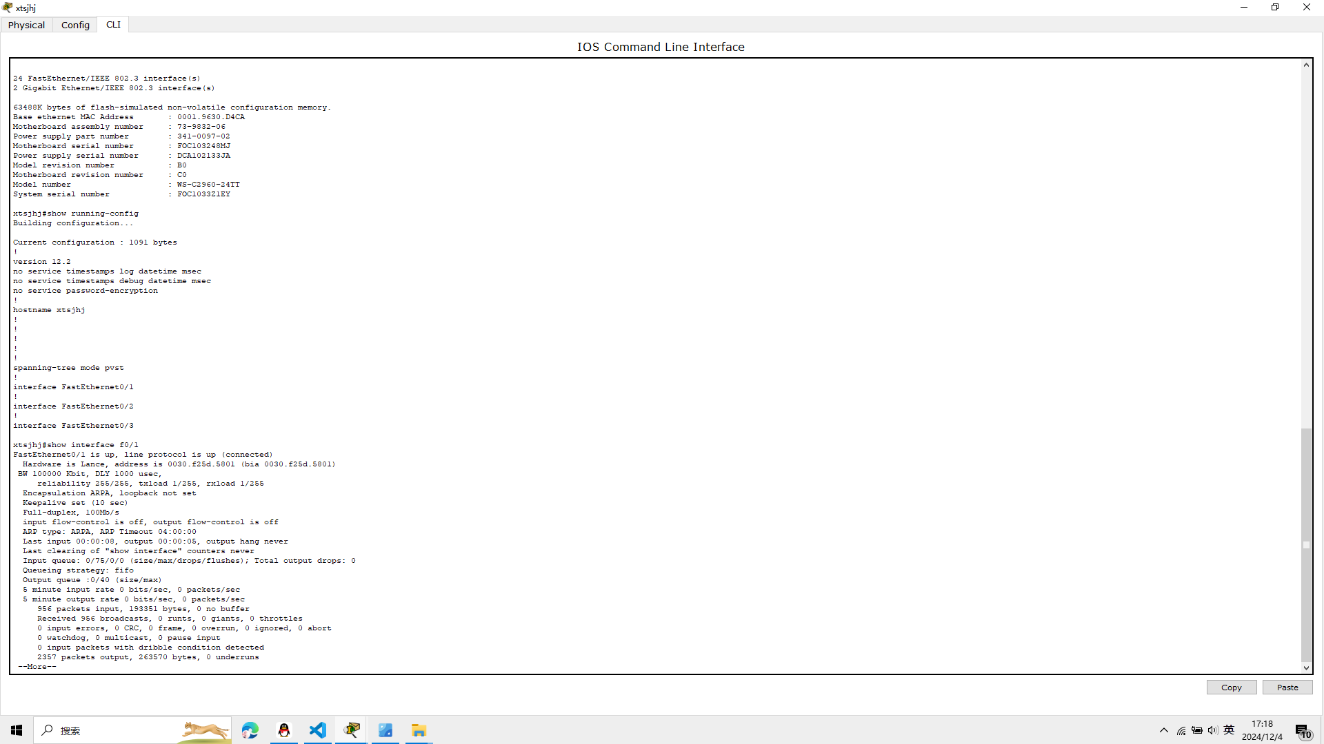
显示交换机的其他信息
命令行输入
show interface f0/1
如图
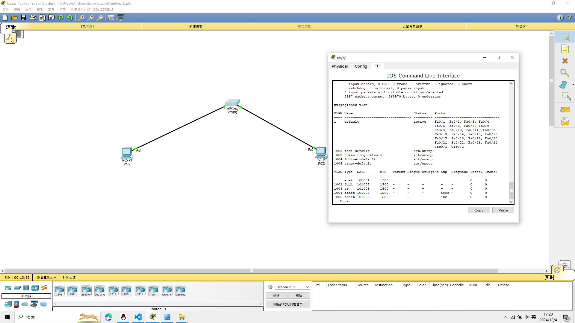
查看vlan
show vlan
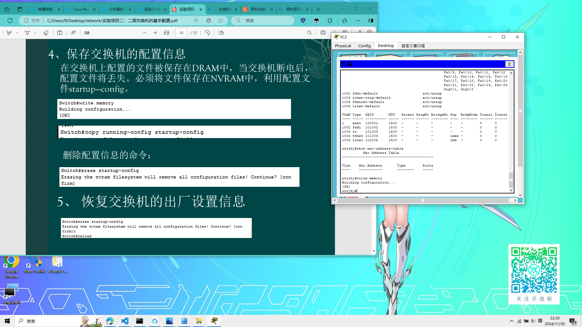
 再次输入
再次输入
show mac-address-table
保存交换机的配置信息
在交换机上配置的文件被保存在DRAM中,当交换机断电后,
配置文件将丢失。必须将文件保存在NVRAM中,利用配置文件startup—config
命令行输入
write memory
如图
 输入
输入
copy running-config startup-config
删除配置信息
命令行输入 erase startup-config
恢复出厂设置
命令行输入
reload
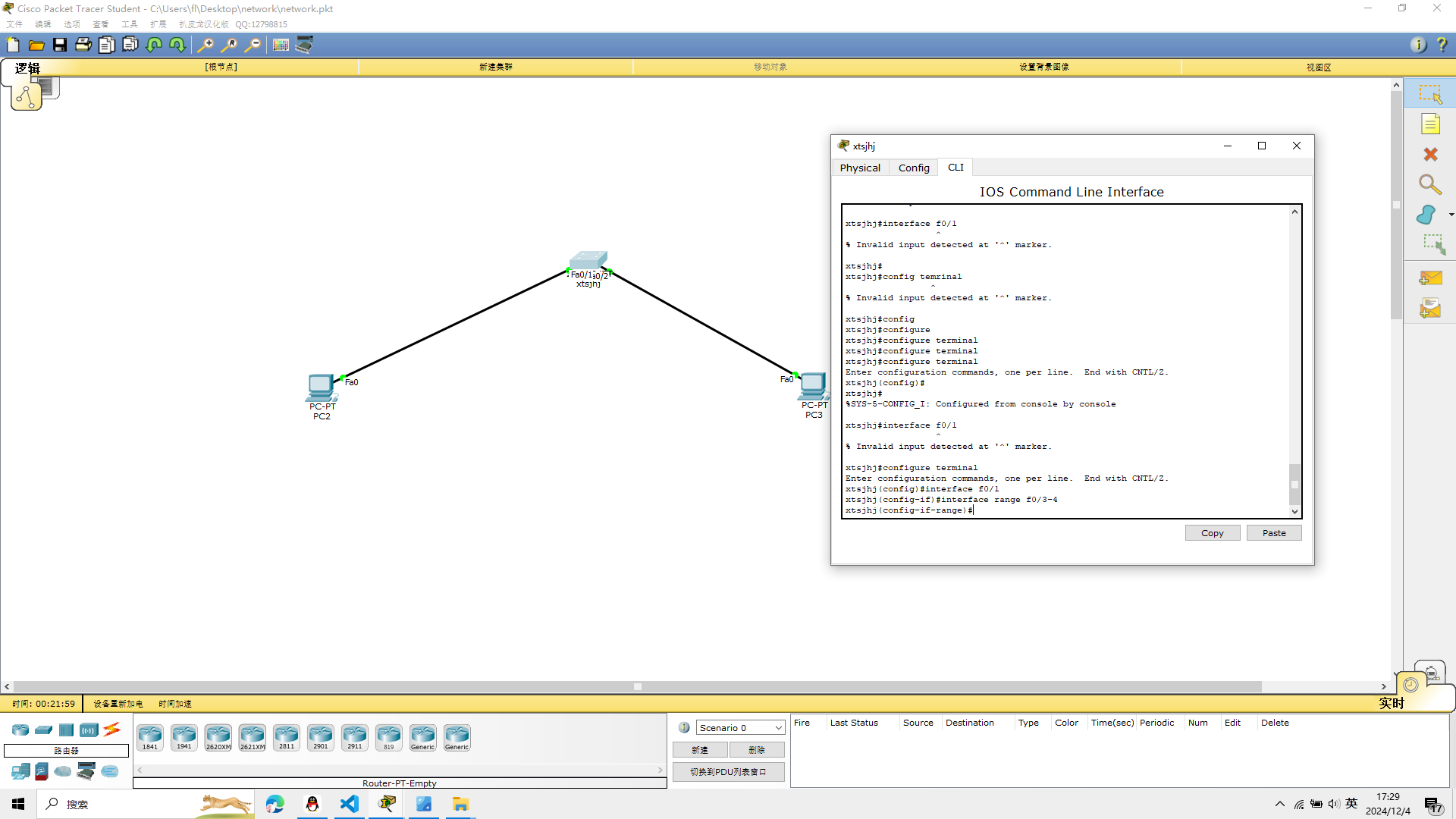
配置交换机的端口
在配置交换机端口的时候
命令行先输入
configure terminal
再输入
interface f0/1
interface range f0/3-4
端口的启用禁用
启用no shutdown
禁用shutdown
端口的通信模式
将端口设置为全双工模式,half为半双工,auto为自动协商。
命令行输入
interface f0/1
duplex full
设置速度
speed 100

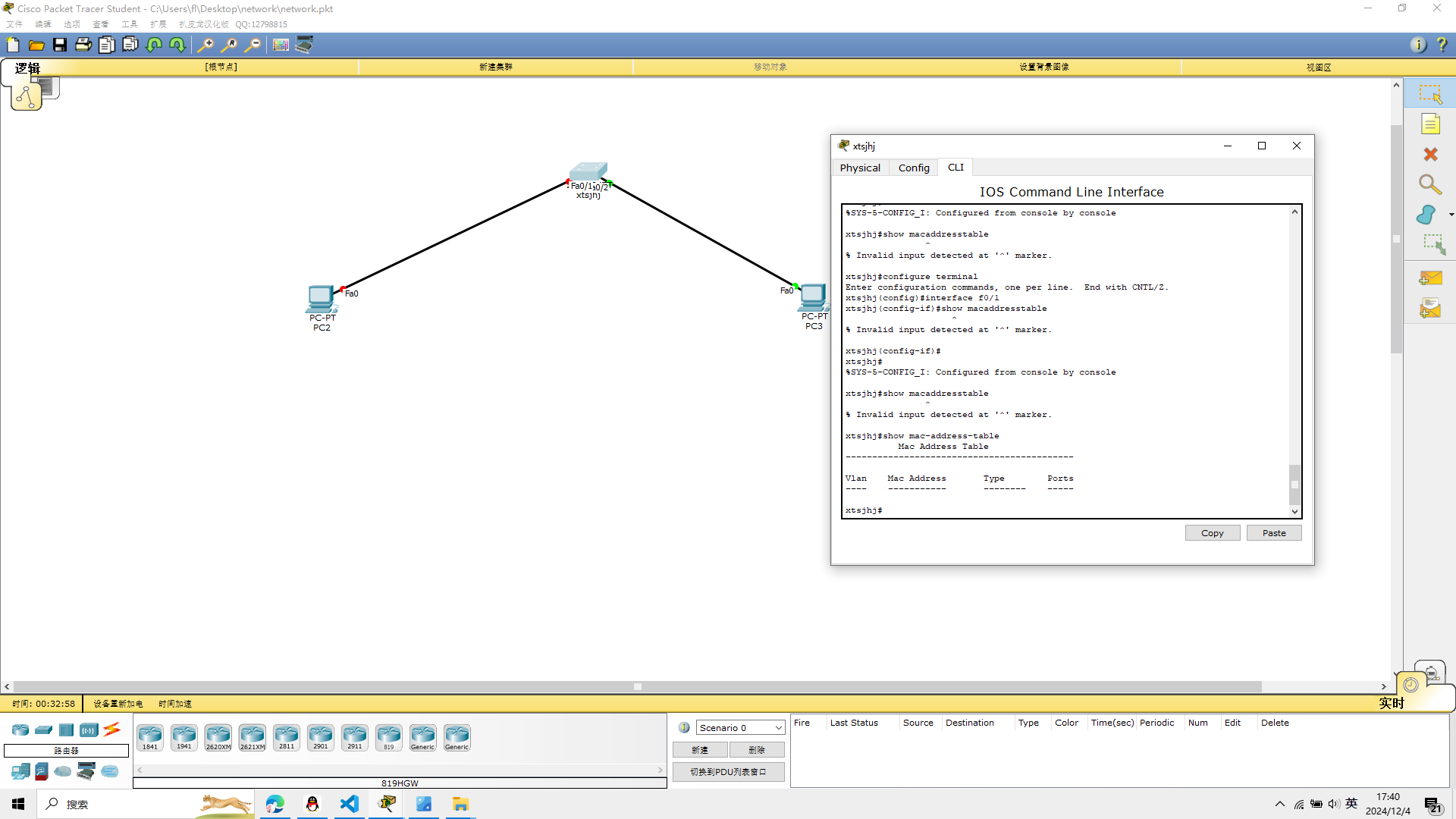
交换机MAC地址表
在特权模式下运行show mac—address—table,此命令可
以显示MAC地址表中的所有MAC地址信息。
输入
show mac—address—table
 实验二大致完成
实验三 虚拟局域网
按照实验三的要求,建立如下的的模型
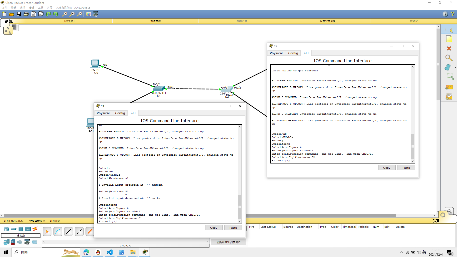
1、将两台交换机分别取名为S1 S2
hostname S1
hostname S2
2、分别在交换机S1和S2上创建VLAN 10和VLAN 20
S1:
vlan 10
vlan 20
进入特权模式
show vlan
查看是否生效
S2:
vlan 10
vlan 20
进入特权模式
show vlan
查看是否生效
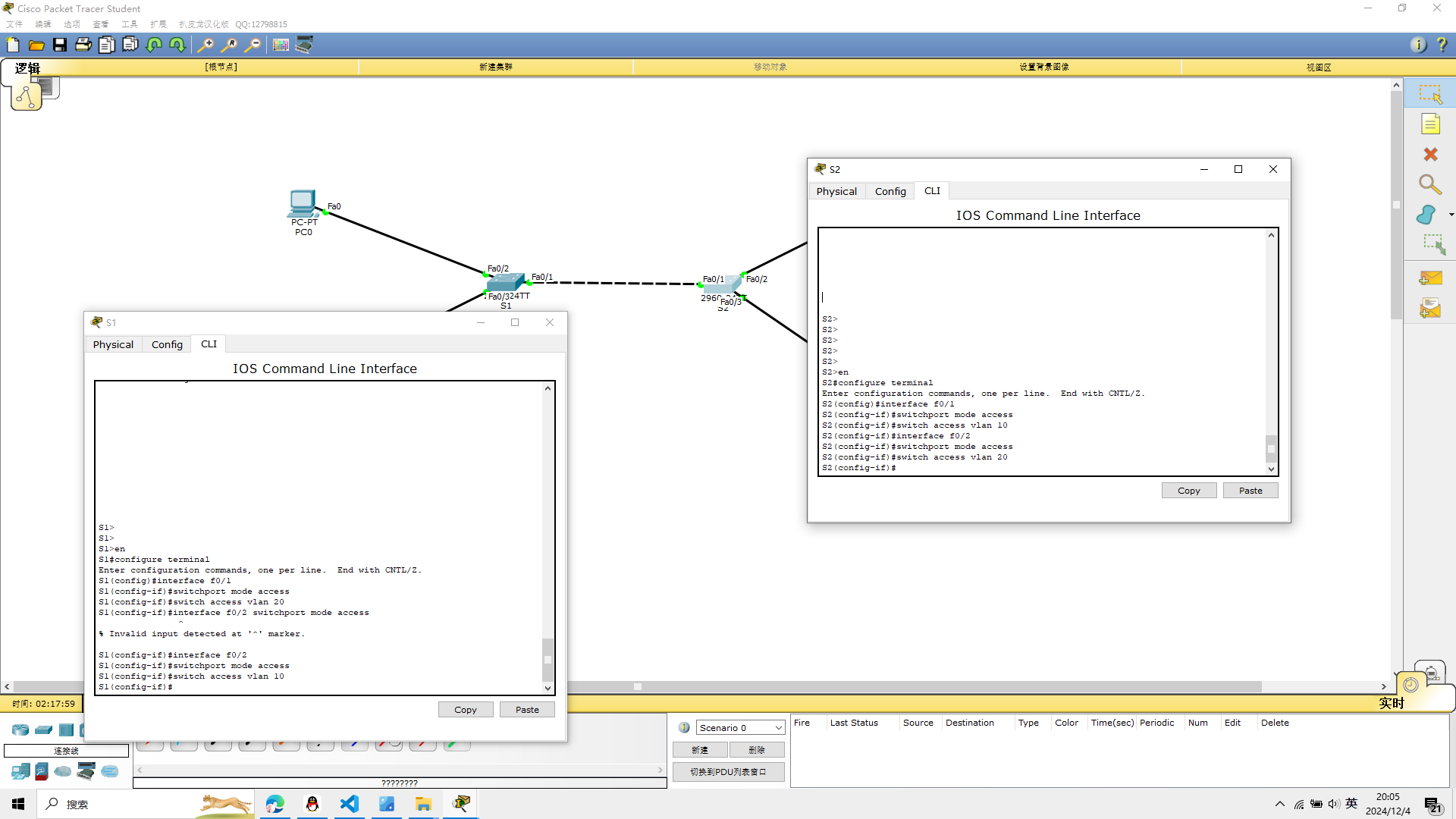
3、将PC机连接的端口加入到相应的VLAN中
交换机S1
在CIL界面输入
将交换机S1中的端口f0/2加入到VLAN 10中,将端口f0/1加入到 VLAN 20中。
configure terminal
interface f0/1
switch access vlan 20
interface f0/2
switch access vlan 10
交换机S2
在CIL界面输入
交换机S2中的端口f0/2加入到VLAN 20中,将端口f0/1加入到 VLAN 10中。
configure terminal
interface f0/1
switch access vlan 10
interface f0/2
switch access vlan 20
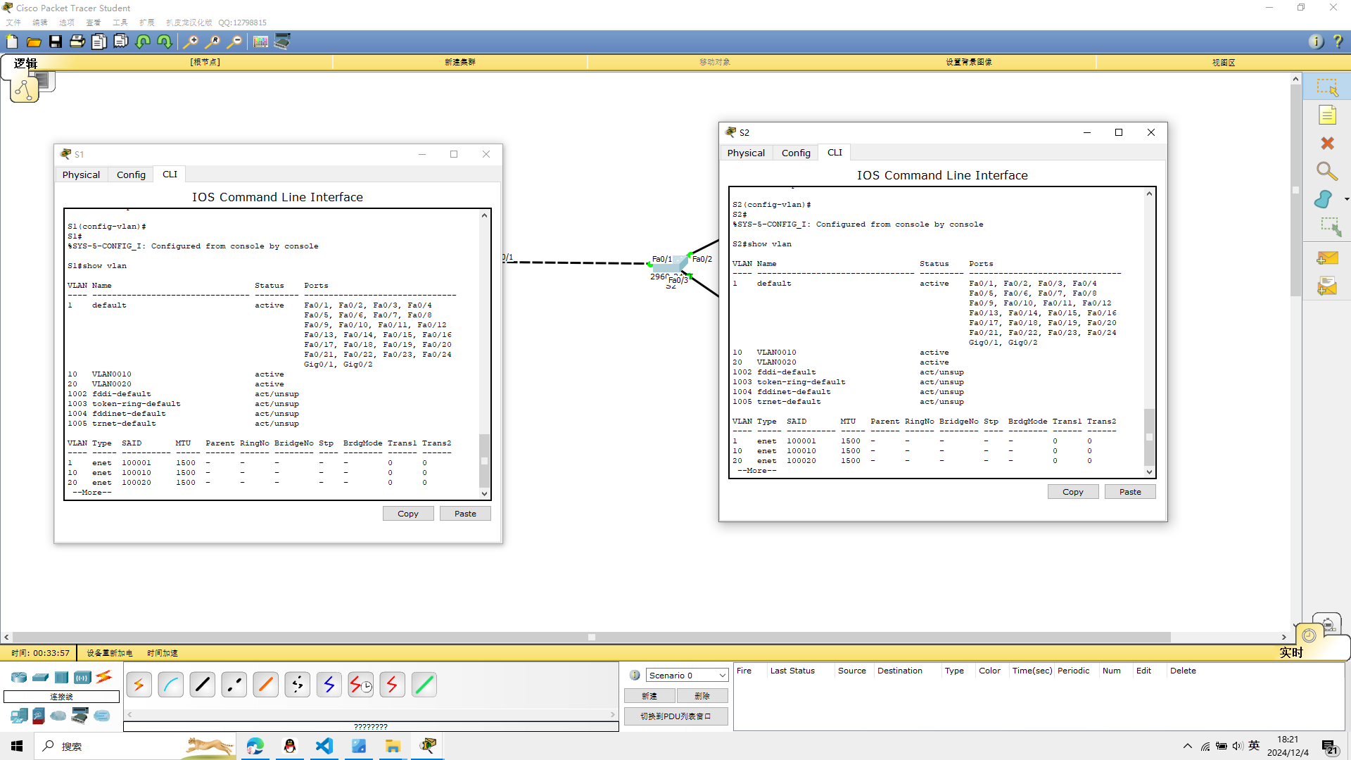
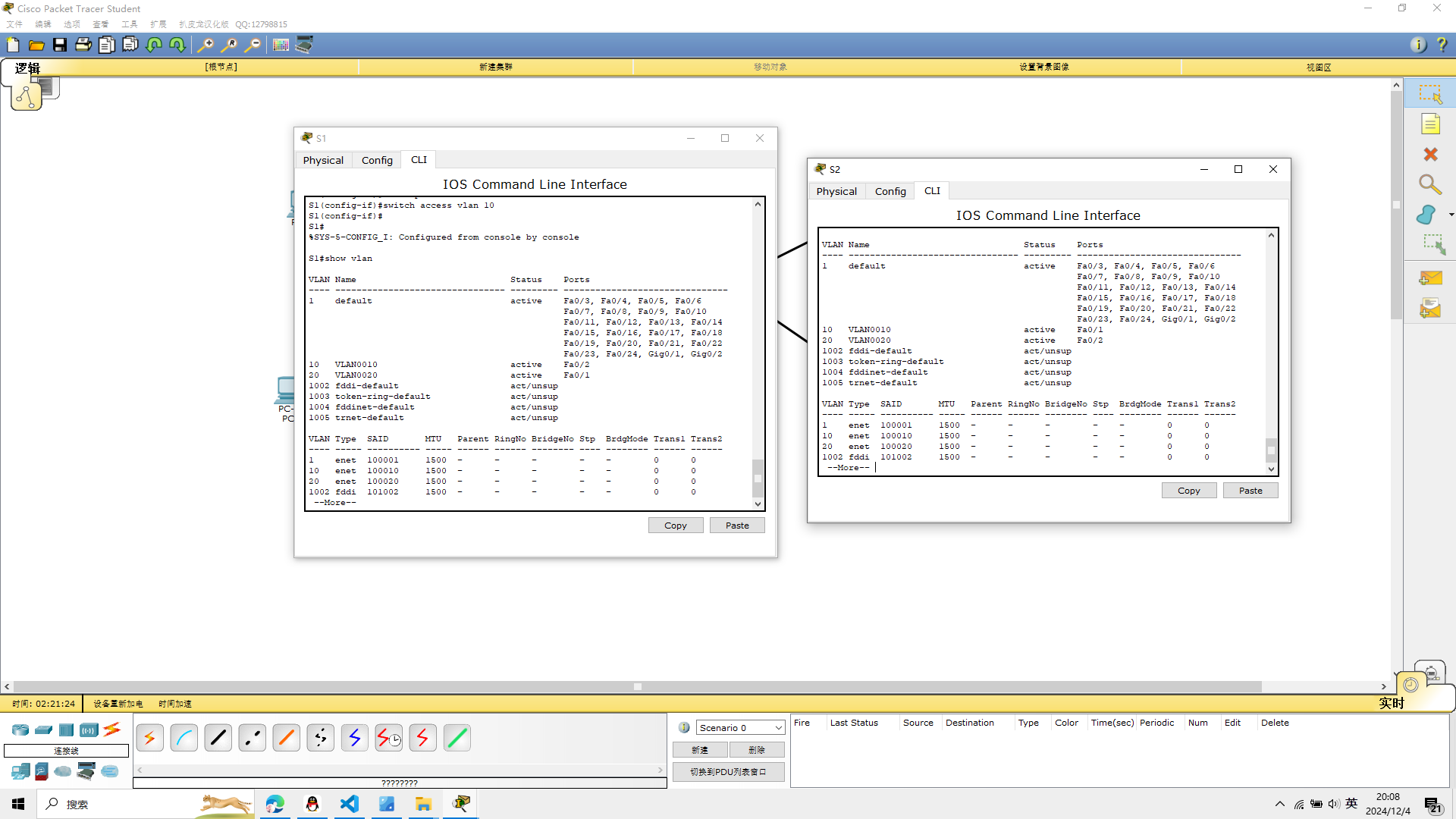
4、查看配置,用show vlan或者show vlan brief
在交换机S1上查看相应的端口是否加入到相应的vlan中
show vlan
在交换机S2上查看相应的端口是否加入到相应的vlan中
show vlan
5、实现同一vlan之间的连通性
交换机S1和交换机S2之间连接的端口进行trunk中继线路
S1
interface f0/3
switchport mode trunk
S2
interface f0/3
switchport mode trunk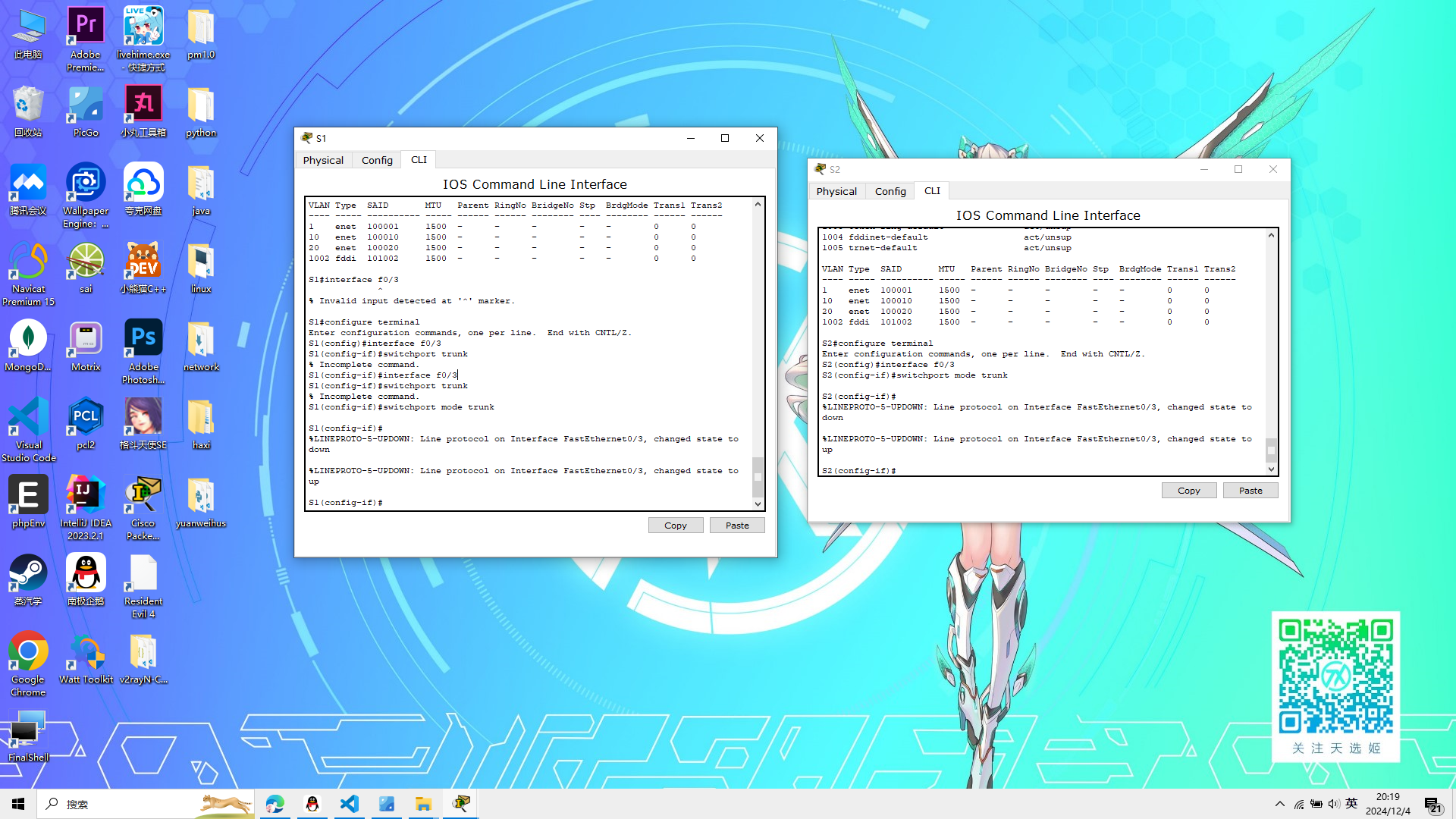
6、配置各PC机的IP地址
pc0 ip
192.168.10.2
pc1 ip
192.168.20.2
pc2 ip
192.168.10.3
pc3 ip
192.168.20.3
子网掩码都是
255.255.255.0

利用ping命令测试网络的连通性
测试主机PC0 与同一vlan的主机PC2的连通性
先配置好,再选择连线
经过本人亲自实验,可行,实验三完成
实验四 三层交换机的配置
在实验三中,我疏忽了一个问题,我没有清晰的展示交换机的cli的的命令行变化,接下来我会注意这个问题
实验四要求我们
Cisco 二层交换机2960两台
Cisco三层交换机3560一台
pc机四台 如图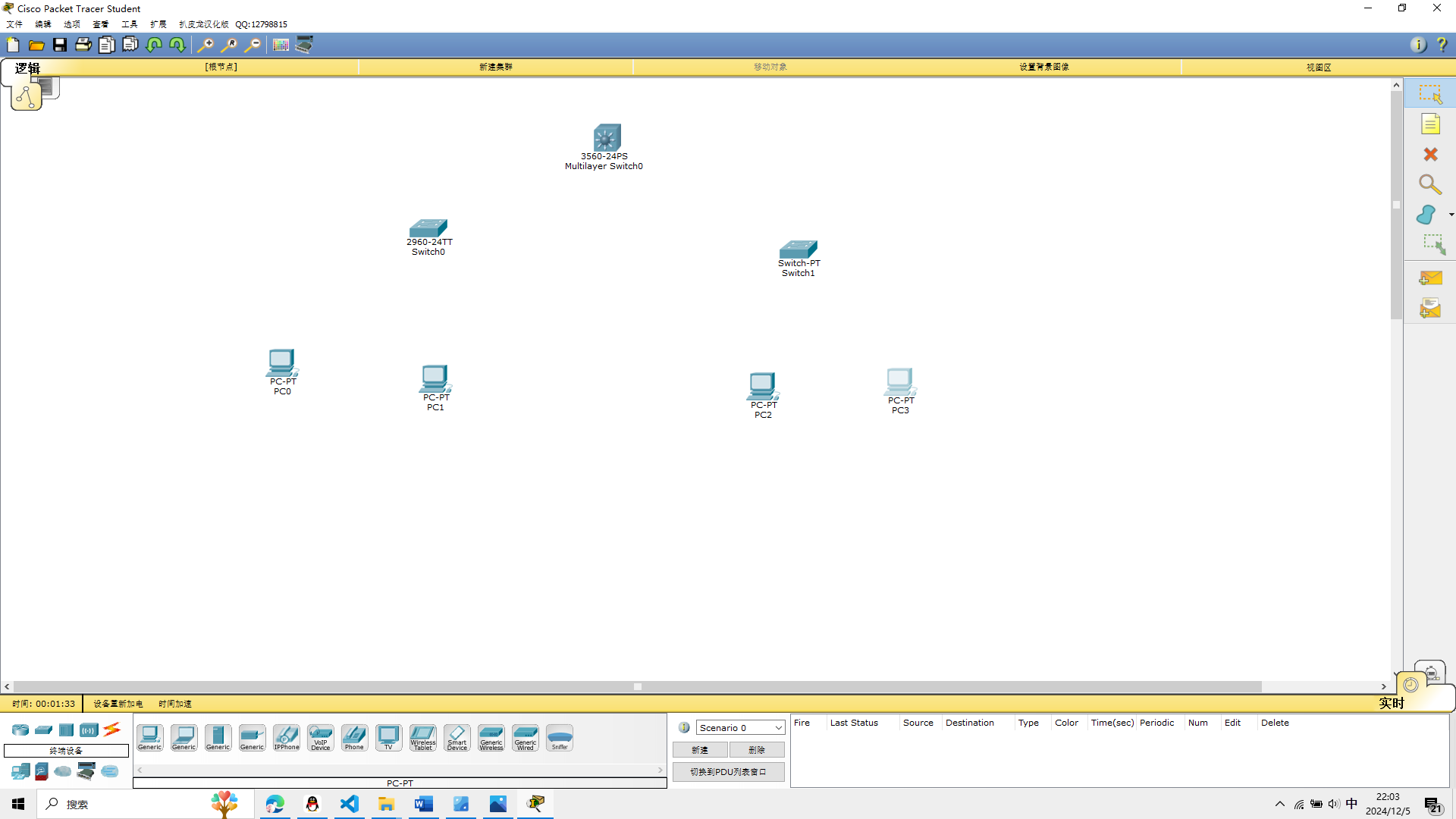
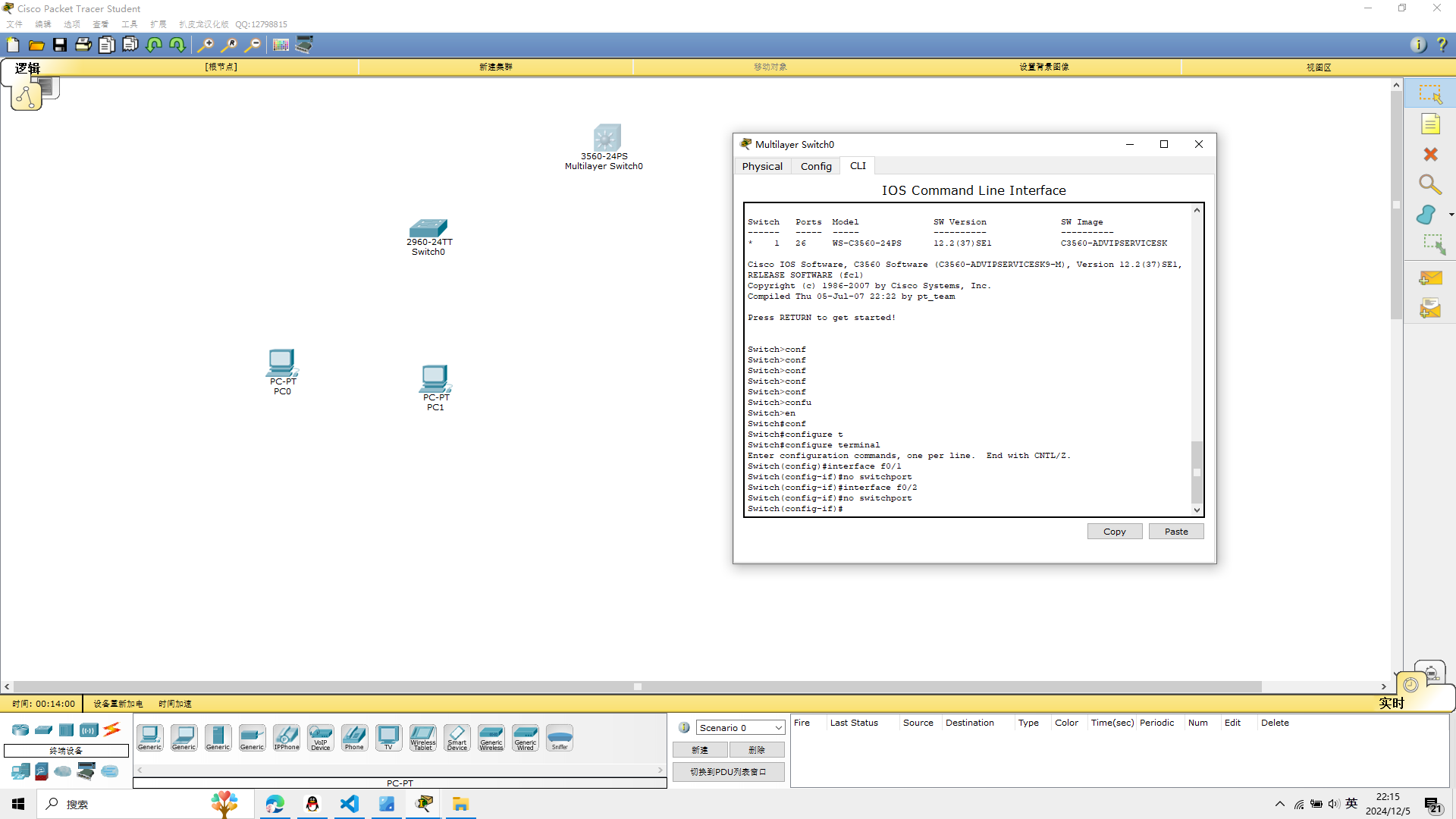
1、将三层交换机的连接端口分别设置为三层接口
使用 no switchport这个命令可以把二层接口改为三层接口
进入3650交换机的cli界面
先将0/1接口设置为三层端口,命令如下
Switch>en
Switch#conf
Switch#configure t
Switch#configure terminal
Enter configuration commands, one per line.  End with CNTL/Z.
Switch(config)#interface f0/1
Switch(config-if)#no switchport
Switch(config-if)#interface f0/2
Switch(config-if)#no switchport
Switch(config-if)#
2、配置三层端口的IP地址
f0/1接口设置IP地址并将端口开启,命令如下
interface f0/1
ip address 192.168.10.1 255.255.255.0
启用(打开)某个网络接口或者某个网络设备
no shutdown
Switch(config-if)#interface f0/1
Switch(config-if)#ip address 192.168.10.1 255.255.255.0
Switch(config-if)#no shutdown
Switch(config-if)#
f0/2接口设置IP地址并将端口开启,命令如下
interface f0/2
ip address 192.168.20.1 255.255.255.0
Switch(config-if)#interface f0/1
Switch(config-if)#ip address 192.168.10.1 255.255.255.0
Switch(config-if)#no shutdown

Switch(config)#interface f0/2
Switch(config-if)#ip address 192.168.20.1 255.255.255.0
Switch(config-if)#
如果要删除某一个端口的IP地址,命令如下:
no ip address
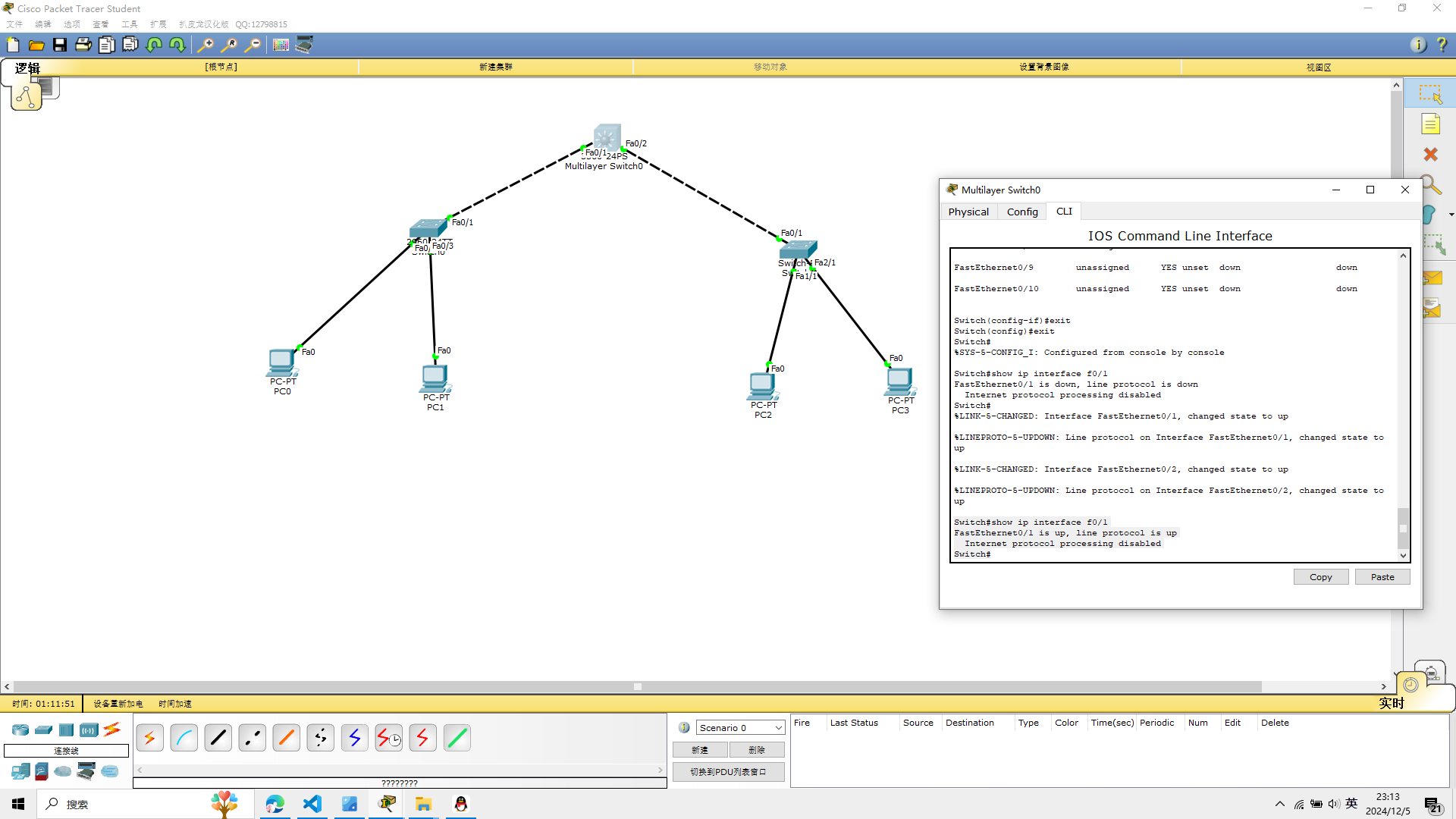
3、显示三层端口的配置信息
在三层交换机上配置好IP地址以后,可以使用命令查看配置信息
利用show ip interface f0/1查看1号端口的IP可用性状态
这里配好后,把线连起来
show ip interface f0/1
Switch#show ip interface f0/1
FastEthernet0/1 is up, line protocol is up
  Internet protocol processing disabled
Switch#
4、PC机的配置
注意:PC机的网关应该是与三层交换机相连接的端口的IP地址
pc0
ip:192.168.10.2
Default Gateway:192.168.10.1
pc1
ip: 192.168.10.3
Default Gateway:192.168.10.1
pc2:
ip:192.168.20.2
Default Gateway:192.168.20.1
pc3: ip:192.168.20.3 Default Gateway:192.168.20.1
subnet mask都为255.255.255.0
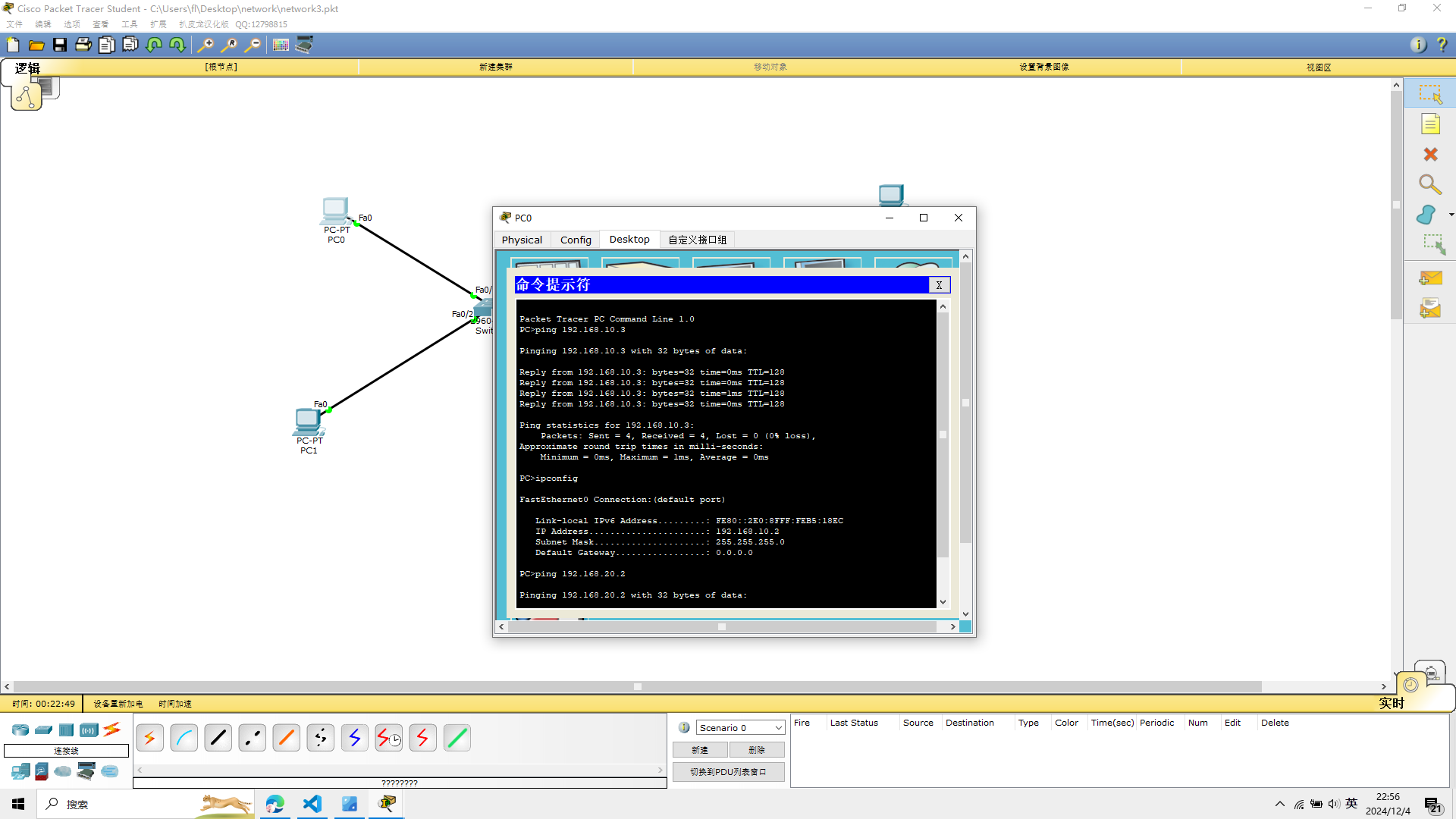
5、验证不同网段之间的连通性
验证主机PC2能ping通PC3,如果能ping通,表示三层交换配置正确
Packet Tracer PC Command Line 1.0
PC>ping 192.168.20.3

Pinging 192.168.20.3 with 32 bytes of data:

Reply from 192.168.20.3: bytes=32 time=0ms TTL=128
Reply from 192.168.20.3: bytes=32 time=0ms TTL=128
Reply from 192.168.20.3: bytes=32 time=0ms TTL=128
Reply from 192.168.20.3: bytes=32 time=1ms TTL=128

Ping statistics for 192.168.20.3:
    Packets: Sent = 4, Received = 4, Lost = 0 (0% loss),
Approximate round trip times in milli-seconds:
    Minimum = 0ms, Maximum = 1ms, Average = 0ms

PC>ipconfig

FastEthernet0 Connection:(default port)

   Link-local IPv6 Address.........: FE80::201:96FF:FECC:B417
   IP Address......................: 192.168.20.2
   Subnet Mask.....................: 255.255.255.0
   Default Gateway.................: 192.168.20.1

PC>
发现轻轻松松

6.思考题
思考:如果在二层交换机上划分虚拟局域网,那么应该设置三层设备
才能实现通信?
我决定建立一个新的模型
如图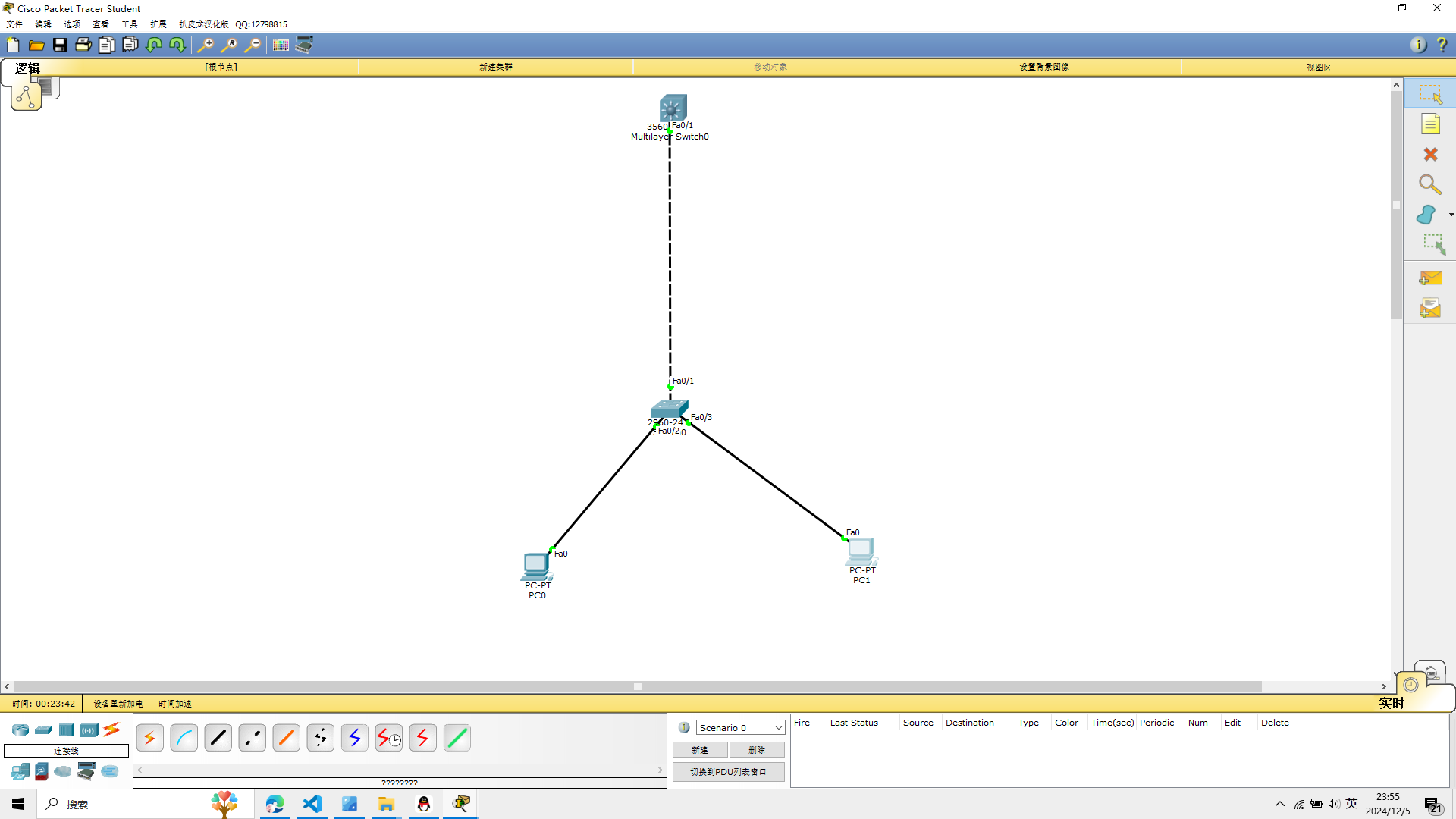
三层设备的端口作为二层接口用,不再作为三层接口使用,不配置IP地址
三层交换机上创建vlan
三层交换机与二层交换机连接的端口需要trunk中继链路
设置明确的封装类型(例如 802.1Q)
通过以下命令设置 trunk 封装类型为 802.1Q:
Switch(config-if)#interface f0/1
Switch(config-if)#switchport mode trunk
Command rejected: An interface whose trunk encapsulation is "Auto" can not be configured to "trunk" mode.
Switch(config-if)#switchport trunk encapsulation dot1q
Switch(config-if)#switchport mode trunk
Switch(config-if)#exit
然后就简单了
Switch(config)#interface vlan 10
Switch(config-if)#ip address 192.168.10.1 255.255.255.0
Switch(config-if)#no shutdown
Switch(config-if)#exit
Switch(config)#interface vlan 20
Switch(config-if)#ip address 192.168.20.1 255.255.255.0
Switch(config-if)#no shutdown
Switch(config-if)#exit
Switch(config)#ip routing
设置pc
pc0
ip 192.168.10.2
pc1
ip 192.168.10.3
子网掩码都是255.255.255.0
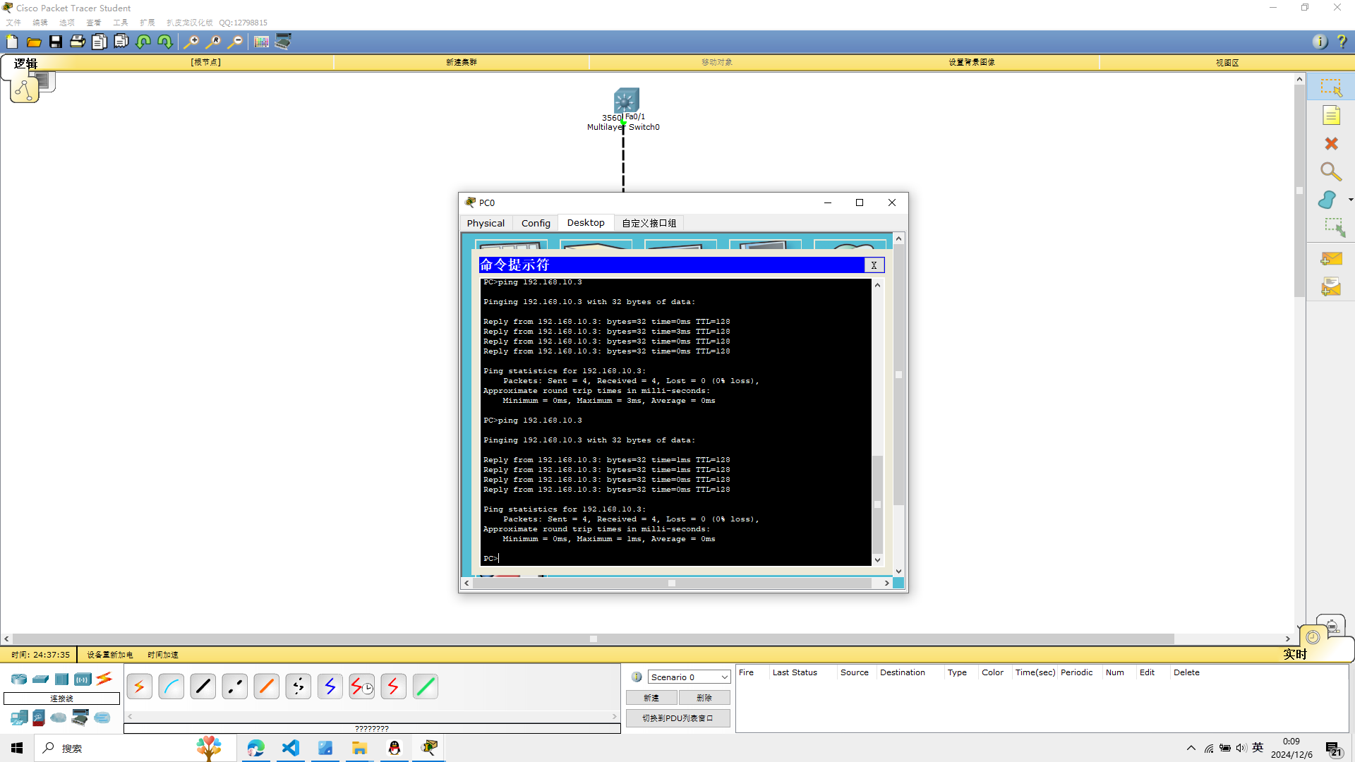
从pc0 ping pc1
PC>ping 192.168.10.3

Pinging 192.168.10.3 with 32 bytes of data:

Reply from 192.168.10.3: bytes=32 time=1ms TTL=128
Reply from 192.168.10.3: bytes=32 time=1ms TTL=128
Reply from 192.168.10.3: bytes=32 time=0ms TTL=128
Reply from 192.168.10.3: bytes=32 time=0ms TTL=128

Ping statistics for 192.168.10.3:
    Packets: Sent = 4, Received = 4, Lost = 0 (0% loss),
Approximate round trip times in milli-seconds:
    Minimum = 0ms, Maximum = 1ms, Average = 0ms
pc>
 实验4完成
实验4完成
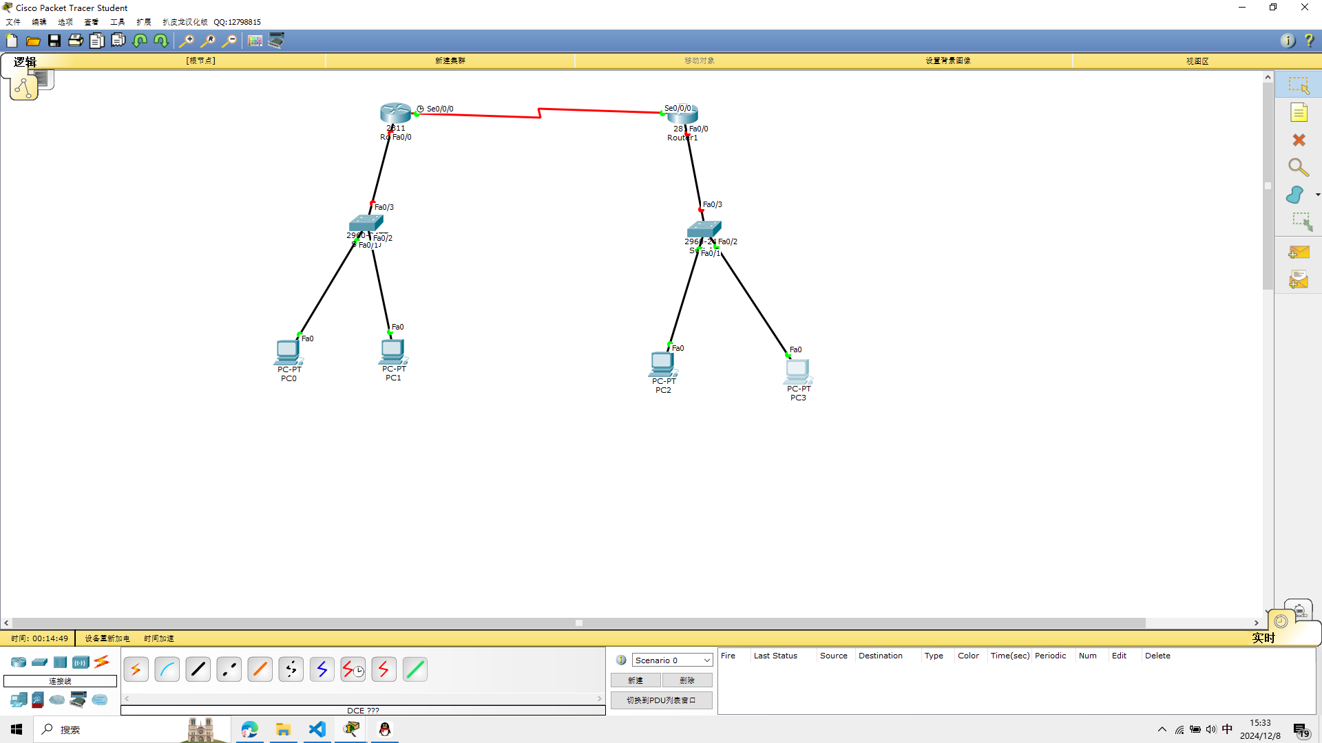
实验五 静态路由的配置
实验设备
Cisco 2811路由器两台
Cisco 2960交换机两台
PC机四台
两台Cisco 2811路由器通过串口端口S0/0/0互连
可以参考这片文章
https://www.jb51.net/network/734207.html
模型如图
1、配置计算机的IP地址
配置计算机PC0—PC3的IP地址信息,计算机的IP地址、子网掩码、网关信息
pc0
ip:192.168.10.2
Default Gateway:192.168.10.1
pc1
ip: 192.168.10.3
Default Gateway:192.168.10.1
pc2
ip:192.168.20.2
Default Gateway:192.168.20.1
pc3
ip:192.168.20.3
Default Gateway:192.168.20.1
subnet mask都为255.255.255.0
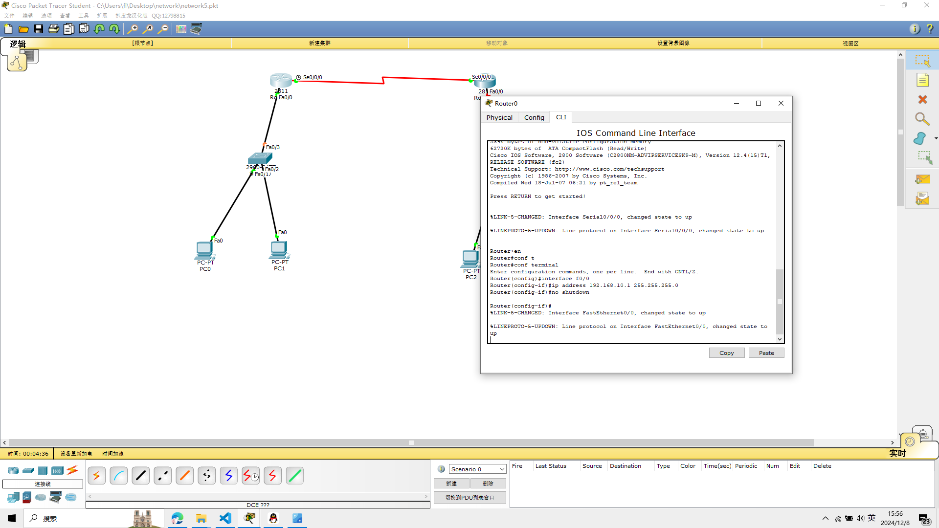
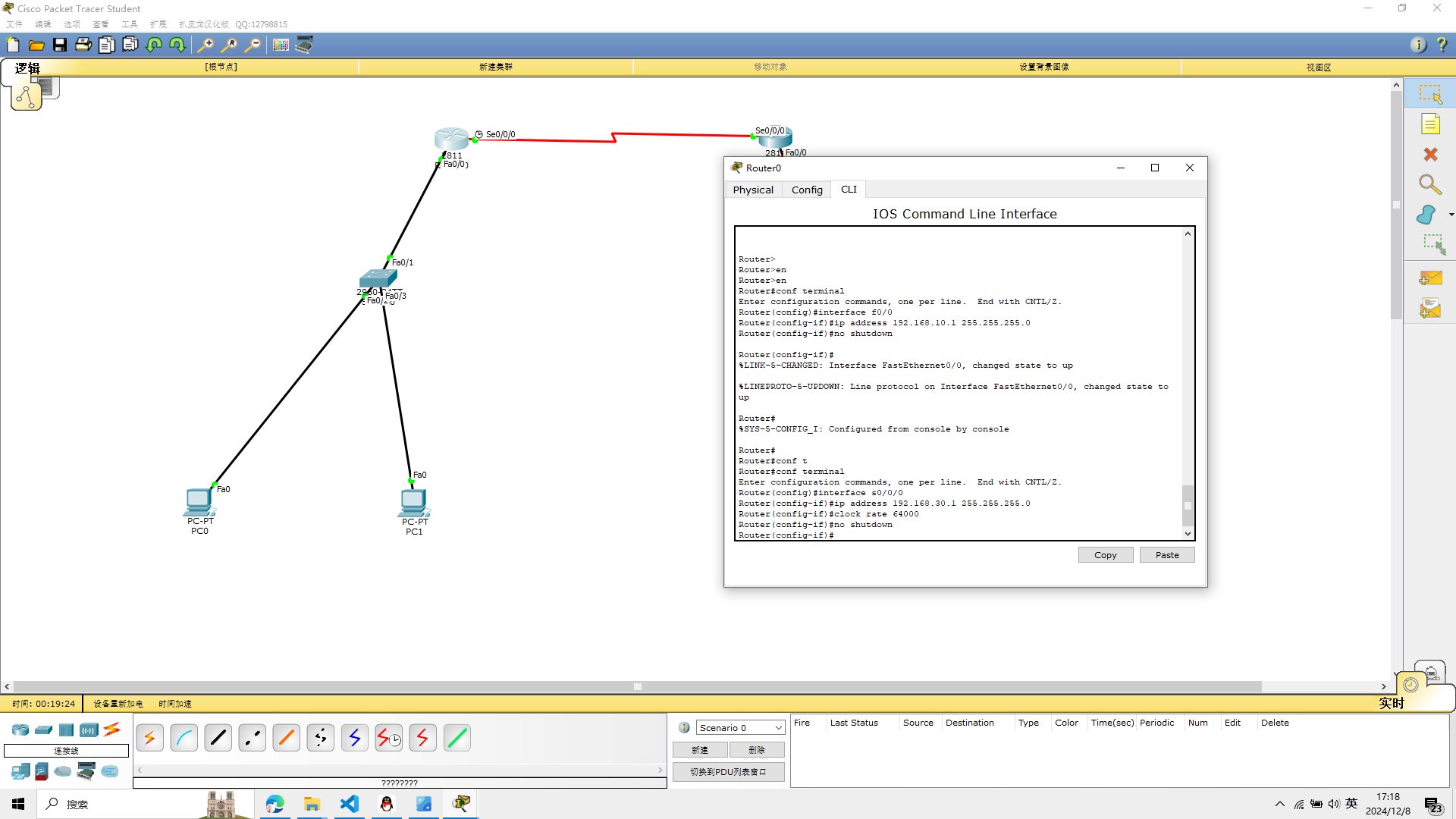
2、配置路由器R0的端口并测试连通性
f0/0接口设置IP地址并将端口开启,命令如下
conf terminal
interface f0/0
ip address 192.168.10.1 255.255.255.0
no shutdown
Router>en
Router#conf t
Router#conf terminal
Enter configuration commands, one per line.  End with CNTL/Z.
Router(config)#interface f0/0
Router(config-if)#ip address 192.168.10.1 255.255.255.0
Router(config-if)#no shutdown

Router(config-if)#
%LINK-5-CHANGED: Interface FastEthernet0/0, changed state to up

%LINEPROTO-5-UPDOWN: Line protocol on Interface FastEthernet0/0, changed state to up
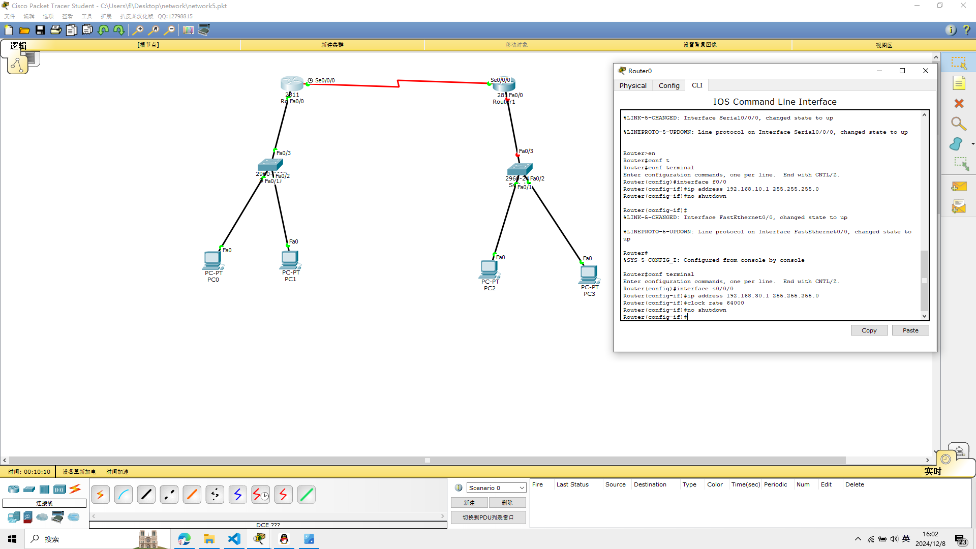
 S0/0/0接口设置IP地址并将端口开启, 同时设置时钟同步,命令如下
conf terminal
interface s0/0/0
ip address 192.168.30.1 255.255.255.0
clock rate 64000
no shutdown
Router#conf terminal
Enter configuration commands, one per line.  End with CNTL/Z.
Router(config)#interface s0/0/0
Router(config-if)#ip address 192.168.30.1 255.255.255.0
Router(config-if)#clock rate 64000
Router(config-if)#no shutdown
Router(config-if)#
如图
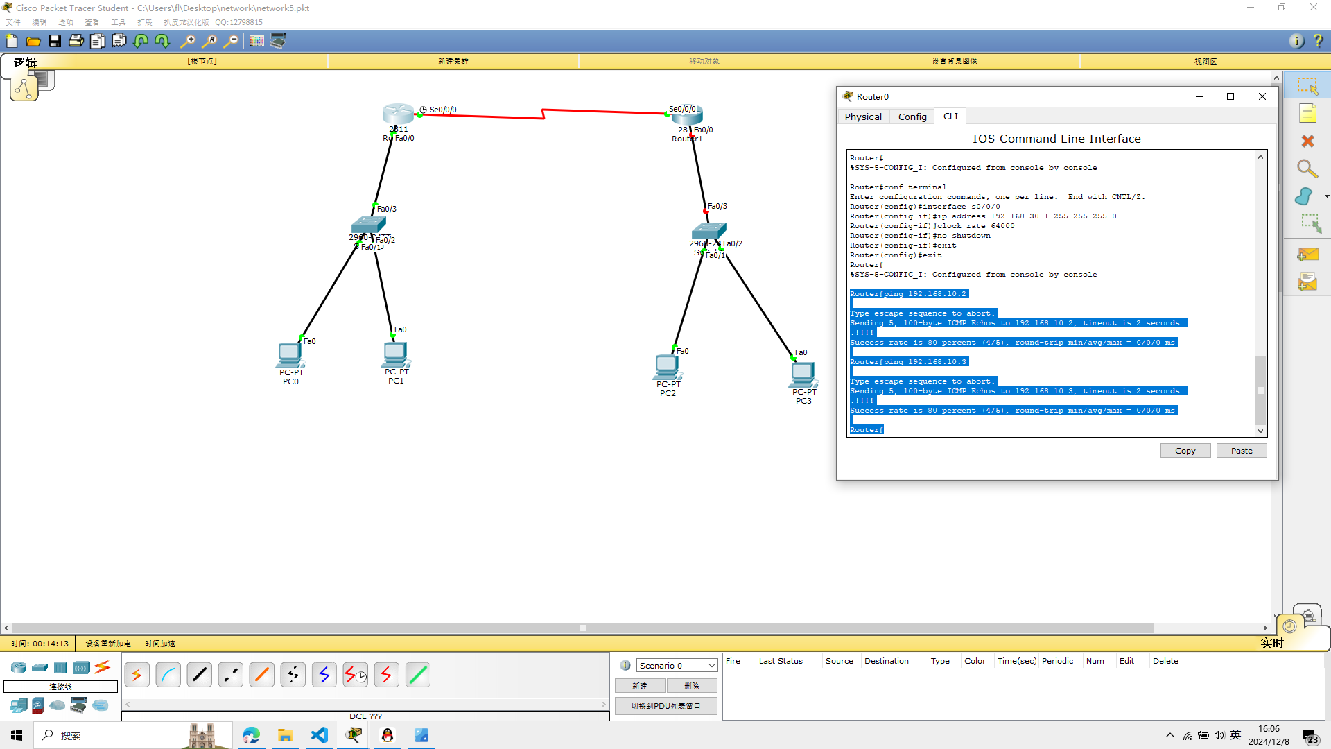
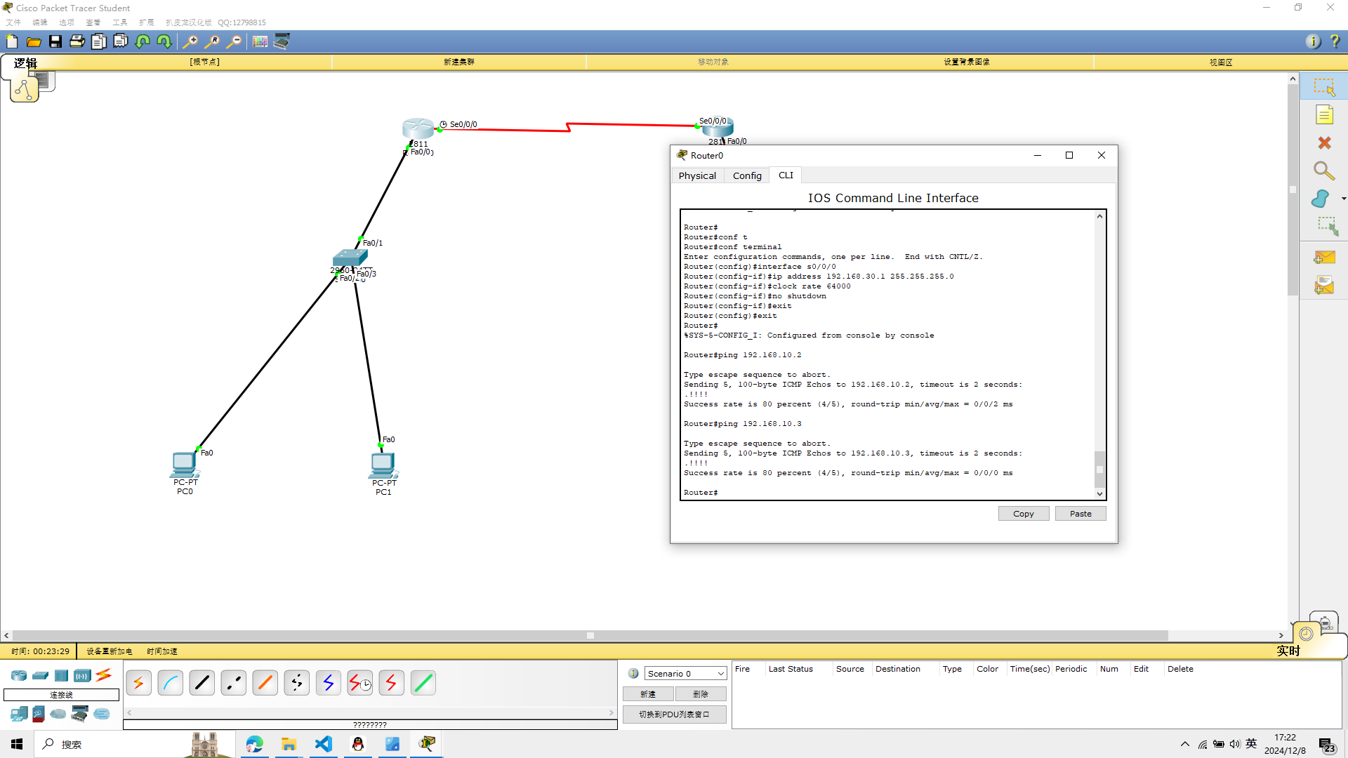
 测试路由器与PC0和PC1的连通性,命令如下
ping 192.168.10.2
ping 192.168.10.3
Router#ping 192.168.10.2

Type escape sequence to abort.
Sending 5, 100-byte ICMP Echos to 192.168.10.2, timeout is 2 seconds:
.!!!!
Success rate is 80 percent (4/5), round-trip min/avg/max = 0/0/0 ms

Router#ping 192.168.10.3

Type escape sequence to abort.
Sending 5, 100-byte ICMP Echos to 192.168.10.3, timeout is 2 seconds:
.!!!!
Success rate is 80 percent (4/5), round-trip min/avg/max = 0/0/0 ms

Router#
可以看到我是成功的
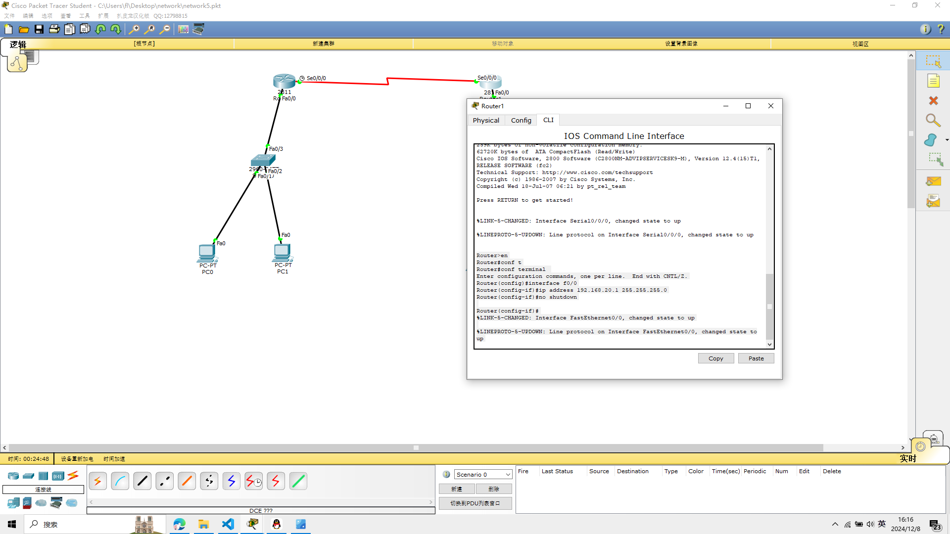
3、配置路由器R1的端口并测试连通性
f0/0接口设置IP地址并将端口开启,命令如下
选择R1路由器
conf terminal
interface f0/0
ip address 192.168.20.1 255.255.255.0
no shutdown
Router>en
Router#conf t
Router#conf terminal
Enter configuration commands, one per line.  End with CNTL/Z.
Router(config)#interface f0/0
Router(config-if)#ip address 192.168.20.1 255.255.255.0
Router(config-if)#no shutdown

Router(config-if)#
%LINK-5-CHANGED: Interface FastEthernet0/0, changed state to up

%LINEPROTO-5-UPDOWN: Line protocol on Interface FastEthernet0/0, changed state to up
 S0/0/0接口设置IP地址并将端口开启, 不设置时钟同步,命令如下
conf terminal
interface s0/0/0
ip address 192.168.30.2 255.255.255.0
no shutdown
Router#conf terminal
Enter configuration commands, one per line.  End with CNTL/Z.
Router(config)#interface s0/0/0
Router(config-if)#ip address 192.168.30.2 255.255.255.0
Router(config-if)#

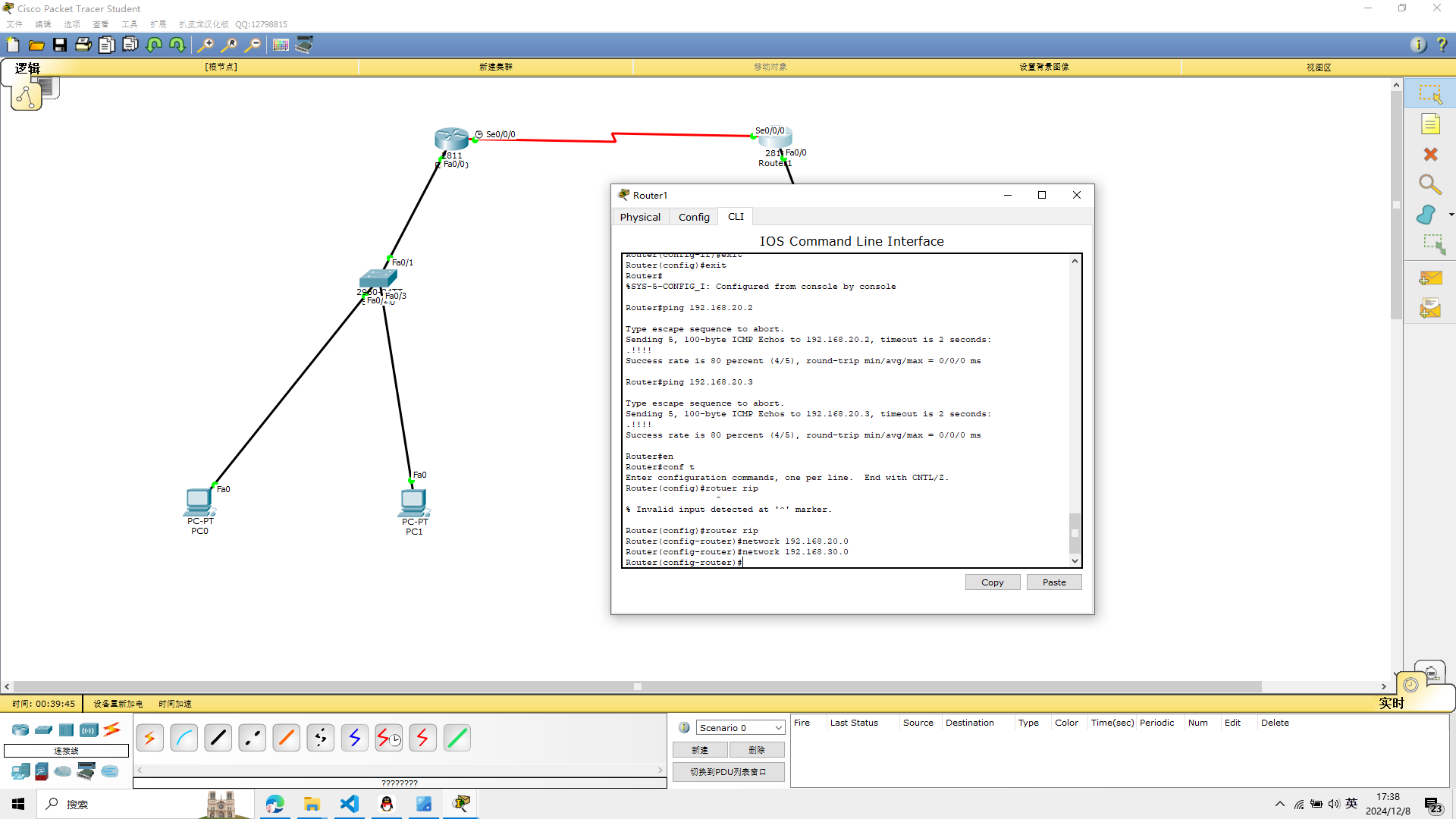
测试路由器与PC2和PC3的连通性 我还是直接上结果吧
Router#ping 192.168.20.2

Type escape sequence to abort.
Sending 5, 100-byte ICMP Echos to 192.168.20.2, timeout is 2 seconds:
.!!!!
Success rate is 80 percent (4/5), round-trip min/avg/max = 0/0/0 ms

Router#ping 192.168.20.3

Type escape sequence to abort.
Sending 5, 100-byte ICMP Echos to 192.168.20.3, timeout is 2 seconds:
.!!!!
Success rate is 80 percent (4/5), round-trip min/avg/max = 0/0/1 ms

Router#
出现的是!!!说明没有出错
此时所有点到点的链路已经连通,但是路由器R0连接的192.168.10.0网络和路由
器R1连接的192.168.20.0网段不能通信。
4、静态路由的配置
R0静态路由信息的配置
ip route 192.168.20.0 255.255.255.0 192.168.30.2
Router(config)#ip route 192.168.20.0 255.255.255.0 192.168.30.2
Router(config)#
R1静态路由信息的配置
ip route 192.168.10.0 255.255.255.0 192.168.30.1
Router(config)#ip route 192.168.10.0 255.255.255.0 192.168.30.1
Router(config)#
5、验证全网的连通性
1、使用traceroute 192.168.20.3,使用该命令,路由器将通过发
送ICMP报文,接收回应报文来测试数据包经过的路由器
在R1路由器上面 输入
traceroute 192.168.20.3,
Router#traceroute 192.168.20.3
Type escape sequence to abort.
Tracing the route to 192.168.20.3

  1   192.168.20.3    0 msec    0 msec    0 msec
Router#
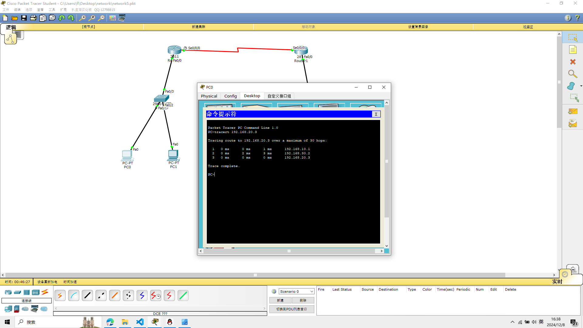
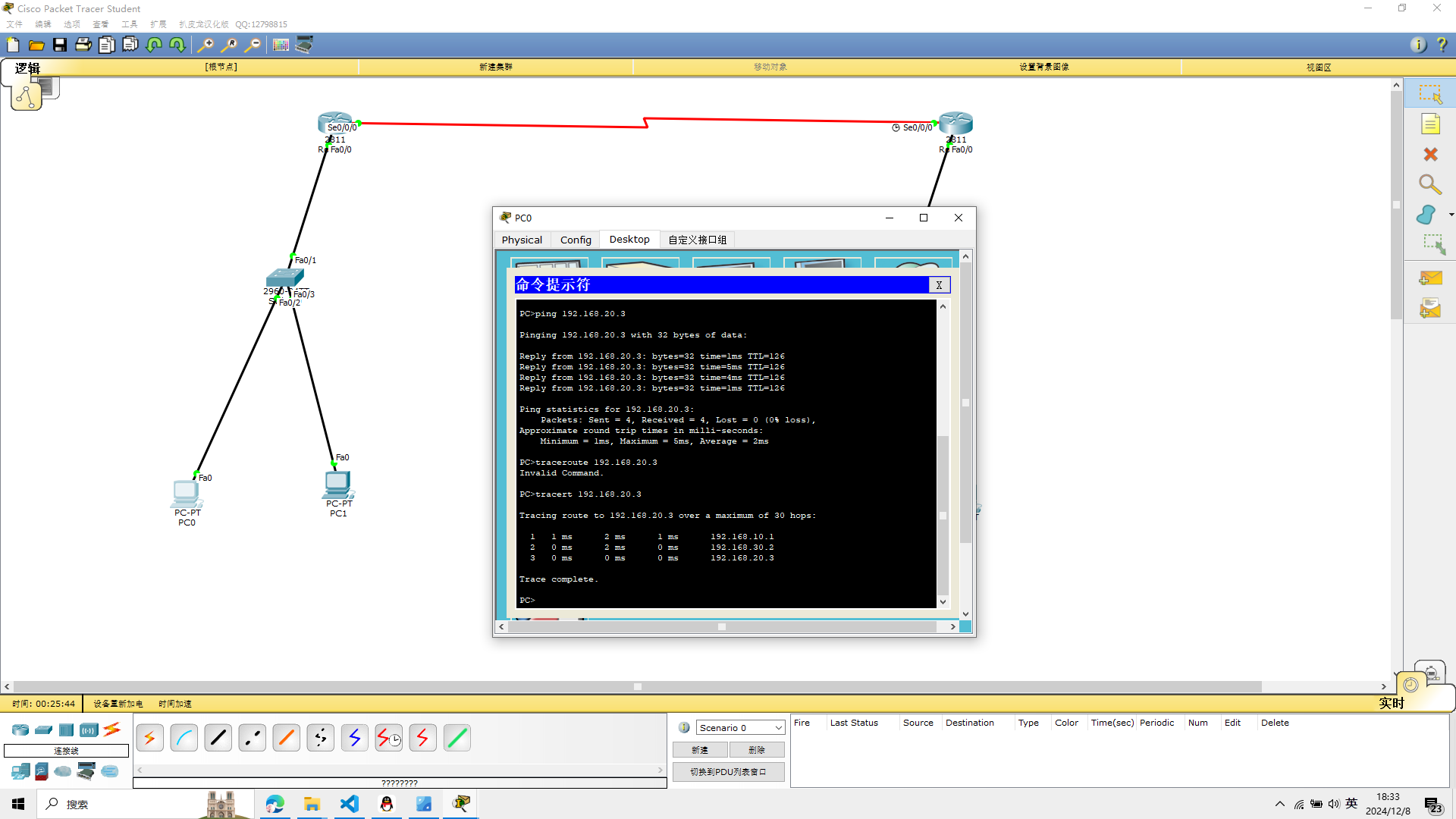
2、在计算机PC0上使用tracert 192.168.20.3,测试PC0与PC3之
间的路由和连通性
在pc0的命令行界面输入
tracert 192.168.20.3
PC>tracert 192.168.20.3

Tracing route to 192.168.20.3 over a maximum of 30 hops:

  1   0 ms      0 ms      1 ms      192.168.10.1
  2   0 ms      2 ms      3 ms      192.168.30.2
  3   0 ms      0 ms      0 ms      192.168.20.3

Trace complete.
实验五完成
实验六 动态路由的配置
和实验五所用的设备相同
Cisco 2811路由器两台
Cisco 2960交换机两台
PC机四台
1 配置计算机的IP地址
配置计算机PC0—PC3的IP地址信息,计算机的IP地址、子网掩码、网关信息
pc0
ip:192.168.10.2
Default Gateway:192.168.10.1
pc1
ip: 192.168.10.3
Default Gateway:192.168.10.1
pc2
ip:192.168.20.2
Default Gateway:192.168.20.1
pc3
ip:192.168.20.3
Default Gateway:192.168.20.1
subnet mask都为255.255.255.0
2、配置路由器R0的端口并测试连通性
f0/0接口设置IP地址并将端口开启,命令如下
conf terminal
interface f0/0
ip address 192.168.10.1 255.255.255.0
no shutdown
Router>en
Router>en
Router#conf terminal
Enter configuration commands, one per line.  End with CNTL/Z.
Router(config)#interface f0/0
Router(config-if)#ip address 192.168.10.1 255.255.255.0
Router(config-if)#no shutdown

Router(config-if)#
%LINK-5-CHANGED: Interface FastEthernet0/0, changed state to up

%LINEPROTO-5-UPDOWN: Line protocol on Interface FastEthernet0/0, changed state to up

Router#
%SYS-5-CONFIG_I: Configured from console by console
S0/0/0接口设置IP地址并将端口开启, 同时设置时钟同步,命令如下
conf terminal
interface s0/0/0
ip address 192.168.30.1 255.255.255.0
clock rate 64000
no shutdown
Router#conf t
Router#conf terminal
Enter configuration commands, one per line.  End with CNTL/Z.
Router(config)#interface s0/0/0
Router(config-if)#ip address 192.168.30.1 255.255.255.0
Router(config-if)#clock rate 64000
Router(config-if)#no shutdown
Router(config-if)#
 测试路由器与PC0和PC1的连通性,命令如下
ping 192.168.10.2
ping 192.168.10.3
Router#ping 192.168.10.2

Type escape sequence to abort.
Sending 5, 100-byte ICMP Echos to 192.168.10.2, timeout is 2 seconds:
.!!!!
Success rate is 80 percent (4/5), round-trip min/avg/max = 0/0/0 ms

Router#ping 192.168.10.3

Type escape sequence to abort.
Sending 5, 100-byte ICMP Echos to 192.168.10.3, timeout is 2 seconds:
.!!!!
Success rate is 80 percent (4/5), round-trip min/avg/max = 0/0/0 ms

Router#
3、配置路由器R1的端口并测试连通性
f0/0接口设置IP地址并将端口开启,命令如下
选择R1路由器
conf terminal
interface f0/0
ip address 192.168.20.1 255.255.255.0
no shutdown
Router>en
Router#conf t
Router#conf terminal
Enter configuration commands, one per line.  End with CNTL/Z.
Router(config)#interface f0/0
Router(config-if)#ip address 192.168.20.1 255.255.255.0
Router(config-if)#no shutdown

Router(config-if)#
%LINK-5-CHANGED: Interface FastEthernet0/0, changed state to up

%LINEPROTO-5-UPDOWN: Line protocol on Interface FastEthernet0/0, changed state to up
S0/0/0接口设置IP地址并将端口开启, 不设置时钟同步,命令如下
conf terminal
interface s0/0/0
ip address 192.168.30.2 255.255.255.0
no shutdown
Router#conf terminal
Enter configuration commands, one per line.  End with CNTL/Z.
Router(config)#interface s0/0/0
Router(config-if)#ip address 192.168.30.2 255.255.255.0
Router(config-if)#
测试路由器与PC2和PC3的连通性 我还是直接上结果吧
Router#ping 192.168.20.2

Type escape sequence to abort.
Sending 5, 100-byte ICMP Echos to 192.168.20.2, timeout is 2 seconds:
.!!!!
Success rate is 80 percent (4/5), round-trip min/avg/max = 0/0/0 ms

Router#ping 192.168.20.3

Type escape sequence to abort.
Sending 5, 100-byte ICMP Echos to 192.168.20.3, timeout is 2 seconds:
.!!!!
Success rate is 80 percent (4/5), round-trip min/avg/max = 0/0/1 ms

Router#
和实验五一样出现的是!!!说明没有出错
此时所有点到点的链路已经连通,但是路由器R0连接的192.168.10.0网络和路由
器R1连接的192.168.20.0网段不能通信。
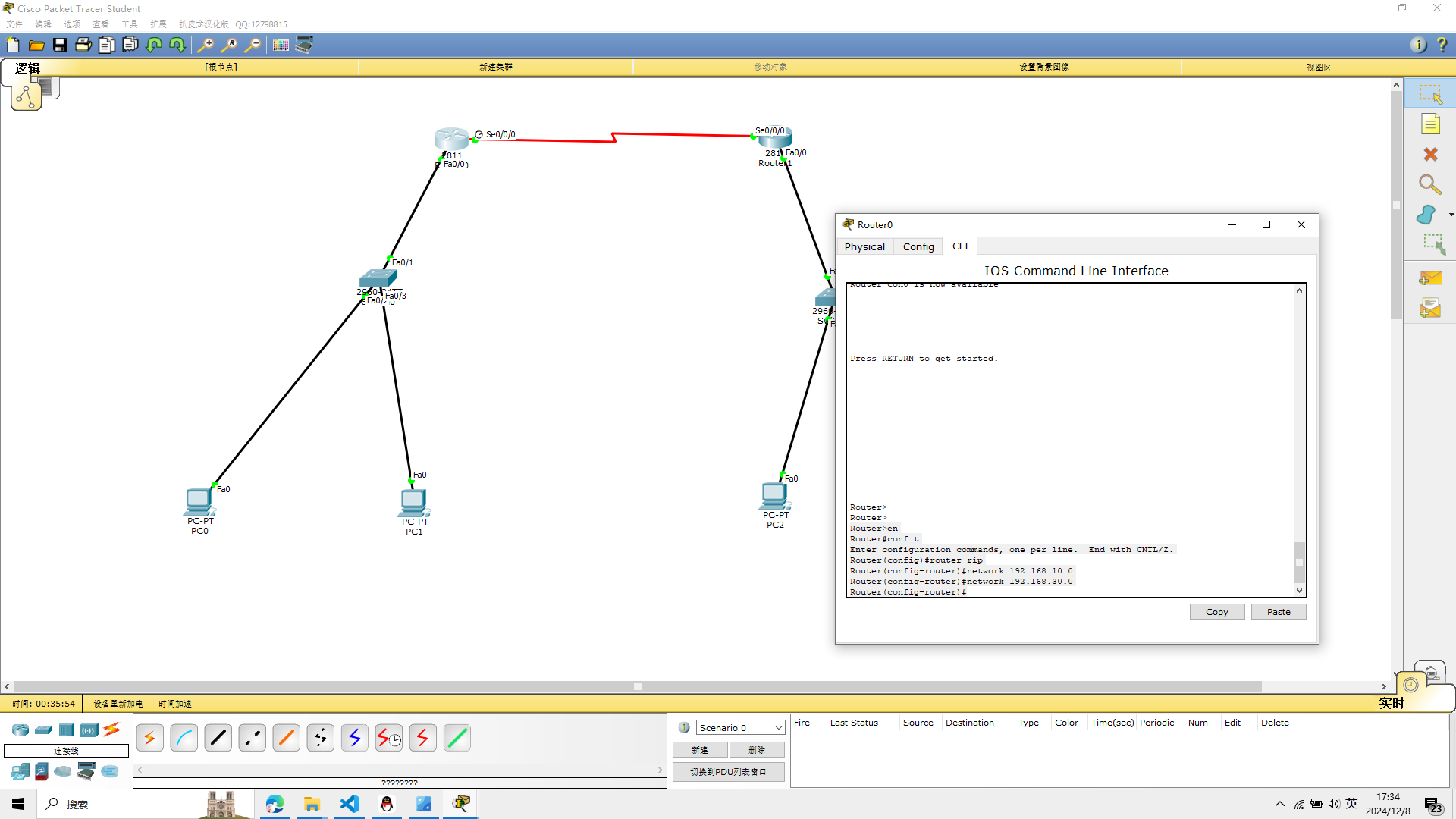
4、动态路由的配置
这里配置是动态路由
R0动态路由信息的配置
conf t
router rip
network 192.168.10.0
network 192.168.30.0
Router>en
Router#conf t
Enter configuration commands, one per line.  End with CNTL/Z.
Router(config)#router rip
Router(config-router)#network 192.168.10.0
Router(config-router)#network 192.168.30.0
Router(config-router)#
 R1动态路由信息的配置
conf t
router rip
network 192.168.20.0
network 192.168.30.0
Router#en
Router#conf t
Enter configuration commands, one per line.  End with CNTL/Z.
Router(config)#rotuer rip
                 ^
% Invalid input detected at '^' marker.

Router(config)#router rip
Router(config-router)#network 192.168.20.0
Router(config-router)#network 192.168.30.0
Router(config-router)#
5、验证RIP
1、如果对RIP进行验证,可以在路由器上查看相关的路由器设置
显示路由器的路由表
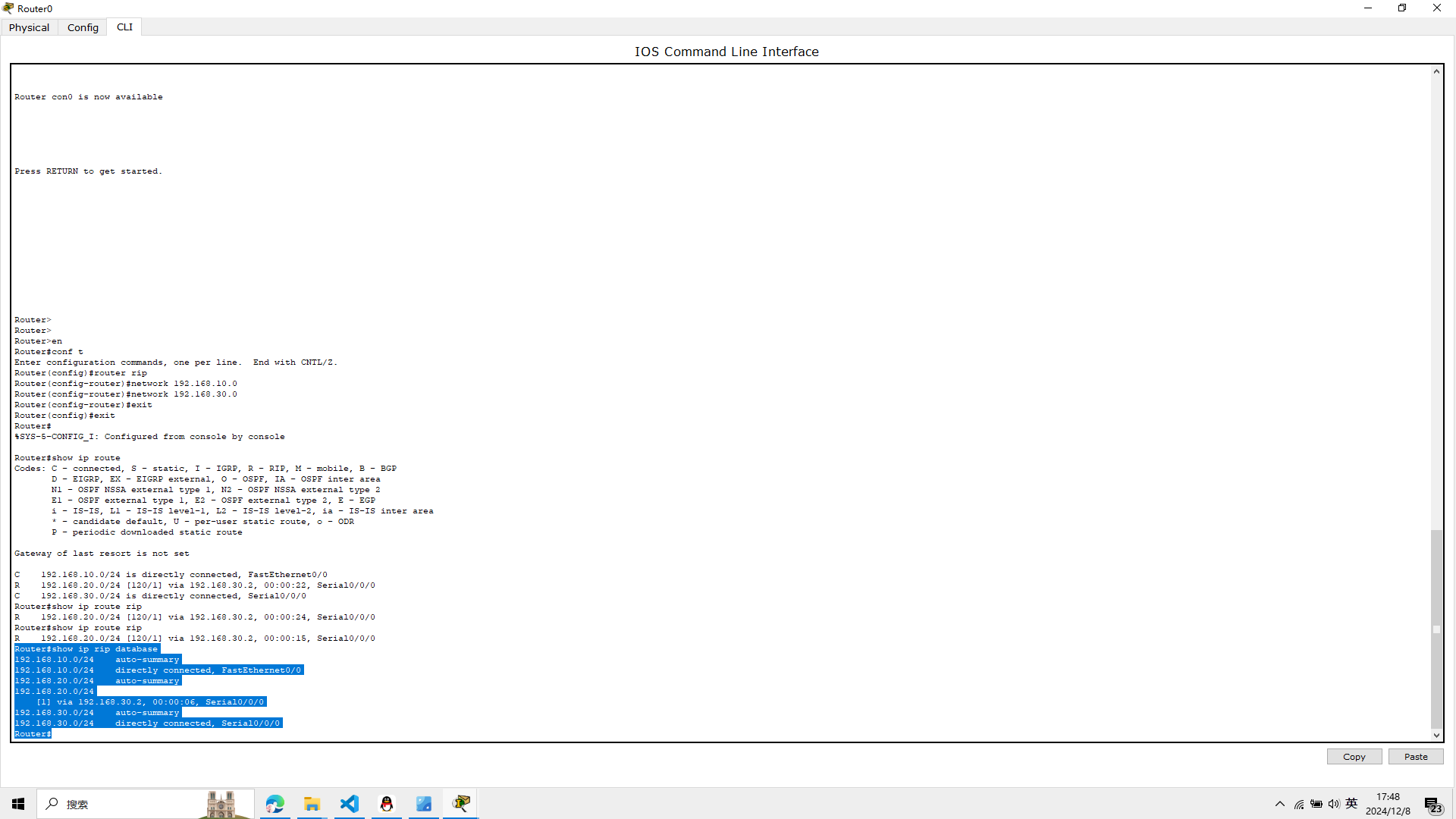
show ip route
Router#show ip route
Codes: C - connected, S - static, I - IGRP, R - RIP, M - mobile, B - BGP
       D - EIGRP, EX - EIGRP external, O - OSPF, IA - OSPF inter area
       N1 - OSPF NSSA external type 1, N2 - OSPF NSSA external type 2
       E1 - OSPF external type 1, E2 - OSPF external type 2, E - EGP
       i - IS-IS, L1 - IS-IS level-1, L2 - IS-IS level-2, ia - IS-IS inter area
       * - candidate default, U - per-user static route, o - ODR
       P - periodic downloaded static route

Gateway of last resort is not set

C    192.168.10.0/24 is directly connected, FastEthernet0/0
R    192.168.20.0/24 [120/1] via 192.168.30.2, 00:00:22, Serial0/0/0
C    192.168.30.0/24 is directly connected, Serial0/0/0
Router#
2、显示路由器的RIP路由
show ip route rip
Router#show ip route rip
R    192.168.20.0/24 [120/1] via 192.168.30.2, 00:00:15, Serial0/0/0
Router#
3、显示RIP路由数据库信息
show ip rip database
Router#show ip rip database
192.168.10.0/24    auto-summary
192.168.10.0/24    directly connected, FastEthernet0/0
192.168.20.0/24    auto-summary
192.168.20.0/24
    [1] via 192.168.30.2, 00:00:06, Serial0/0/0
192.168.30.0/24    auto-summary
192.168.30.0/24    directly connected, Serial0/0/0
Router#
6、验证全网的连通性
1、使用traceroute 192.168.20.3,使用该命令,路由器将通过发
送ICMP报文,接收回应报文来测试数据包经过的路由器
在R1路由器输入
traceroute 192.168.20.3
Router#traceroute 192.168.20.3
Type escape sequence to abort.
Tracing the route to 192.168.20.3

  1   192.168.20.3    0 msec    0 msec    0 msec
Router#
2、在计算机PC0上使用tracert 192.168.20.3
测试PC0与PC3之
间的路由和连通性
打开pc0的命令行界面 输入
tracert 192.168.20.3
tracert 192.168.20.2
实验6完成
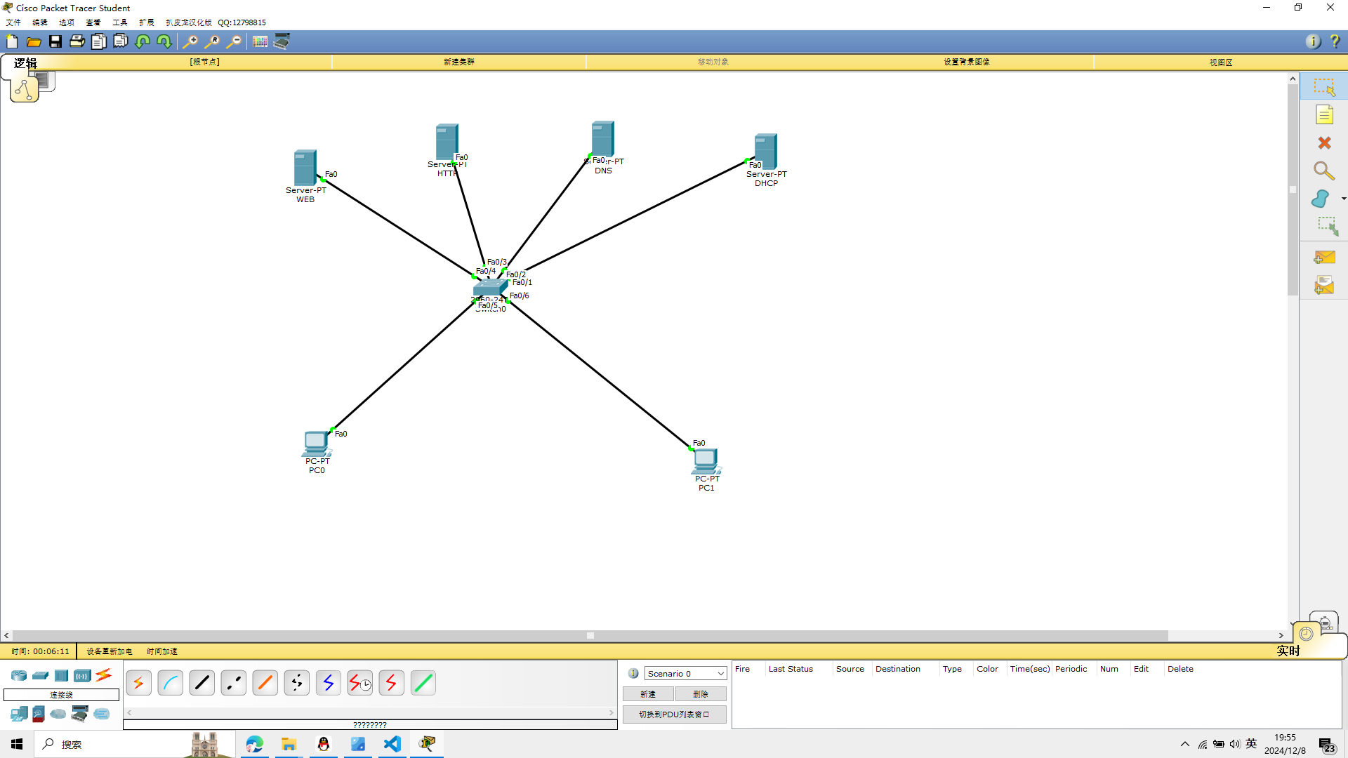
实验七 DHCP的配置
实验所需的设备
Cisco 2960交换机1台
服务器4台
PC机2台
如图
1、配置服务器的IP地址
DHCP server
ip 192.168.10.1
subnet mask 255.255.255.0
DNS server
ip 192.168.10.2
subnet mask 255.255.255.0
FTP server
ip 192.168.10.3
subnet mask 255.255.255.0
WEB server
ip 192.168.10.4
subnet mask 255.255.255.0
服务器名字打错了,已经修正
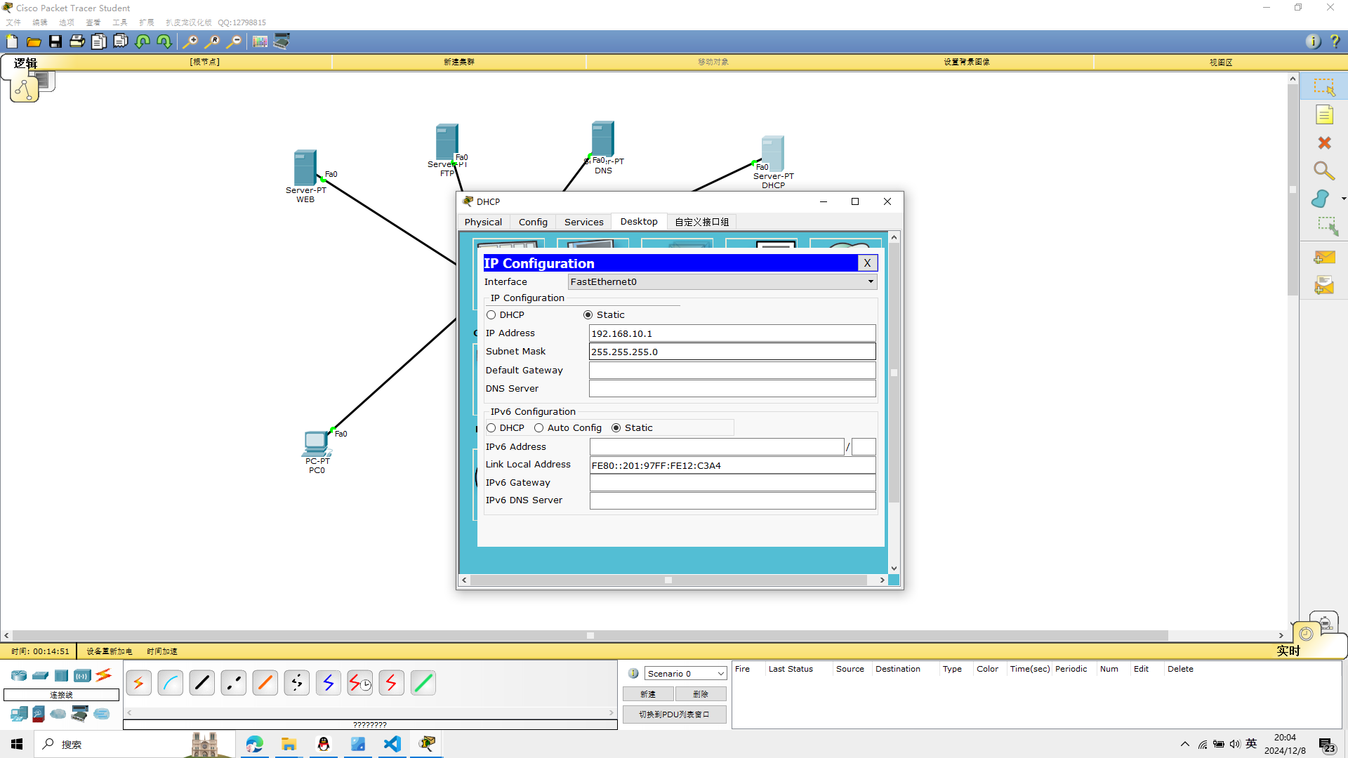 依次录入IP
2、DHCP配置
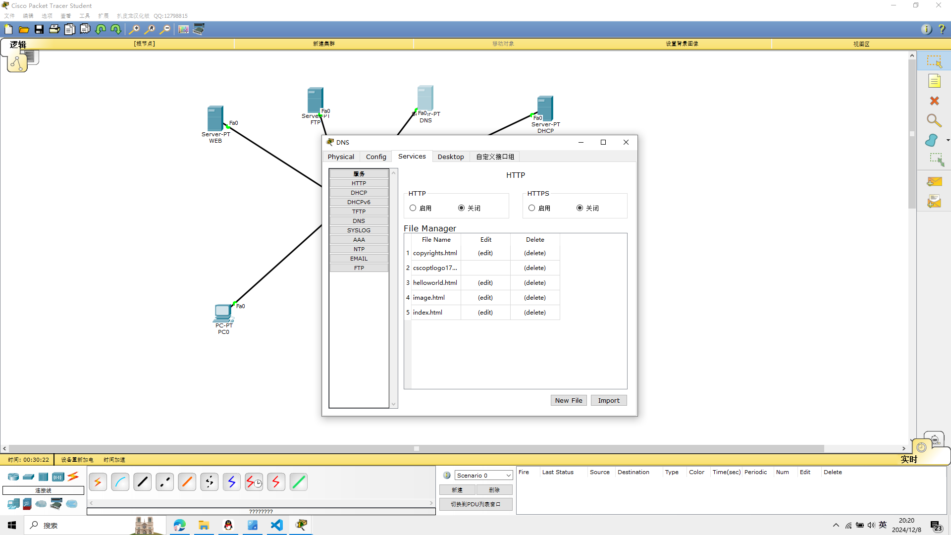
配置DHCP服务器,关闭服务器上的DNS、FTP、WEB服务,其他服务不变
web服务和http相等,关闭它
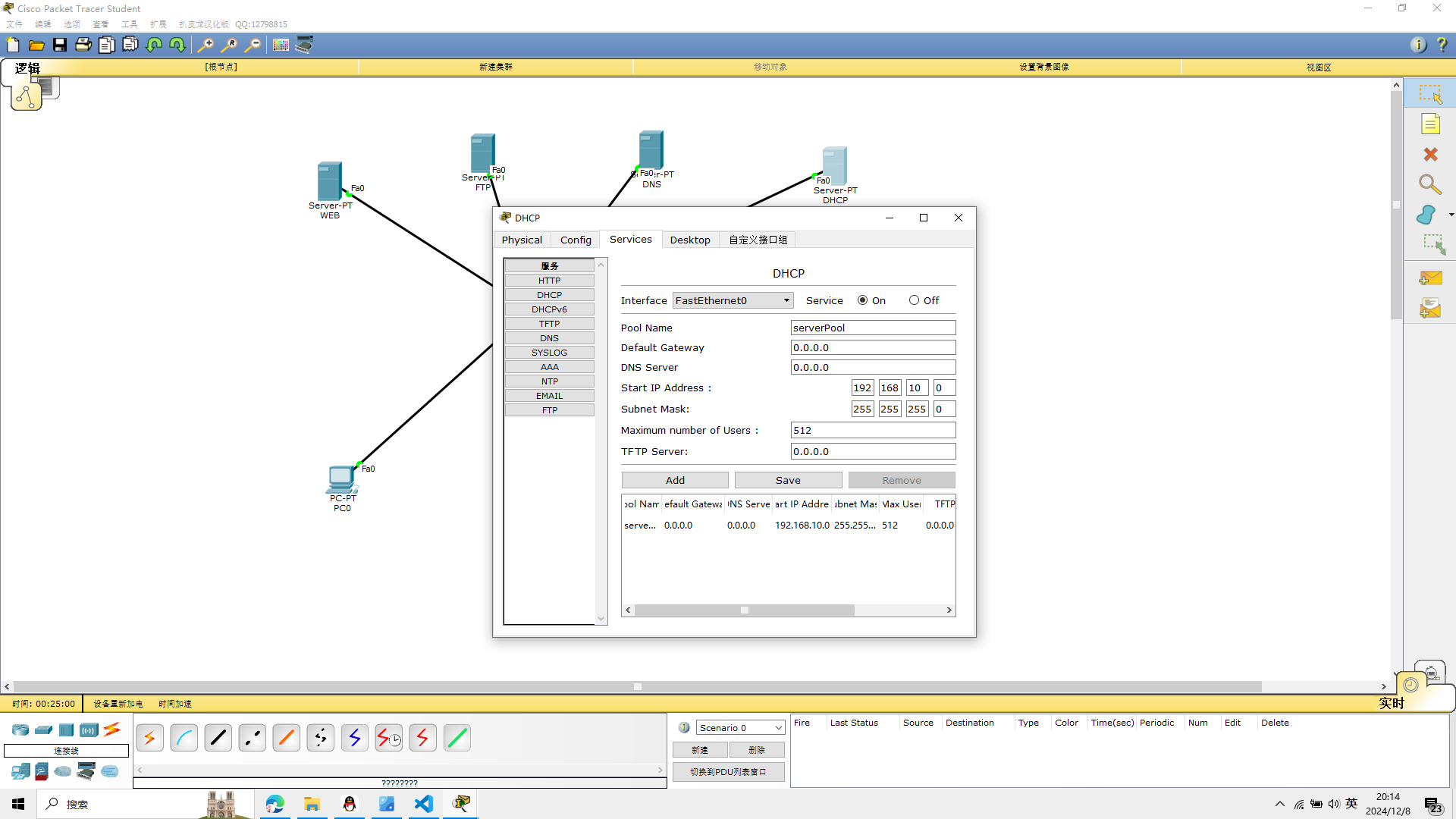
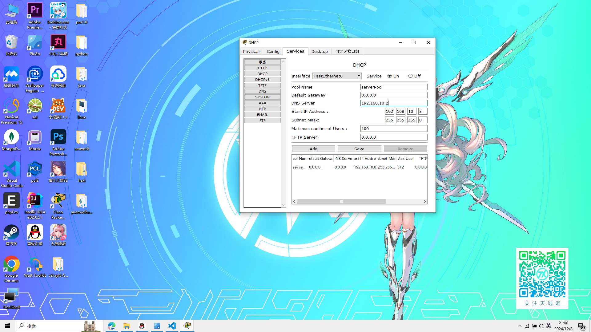
点击左侧的DHCP,然后Server点击on,默认网关:0.0.0.0,
DNS Server为192.168.10.2,开始地址为192.168.10.5,子网最大客户端为100.
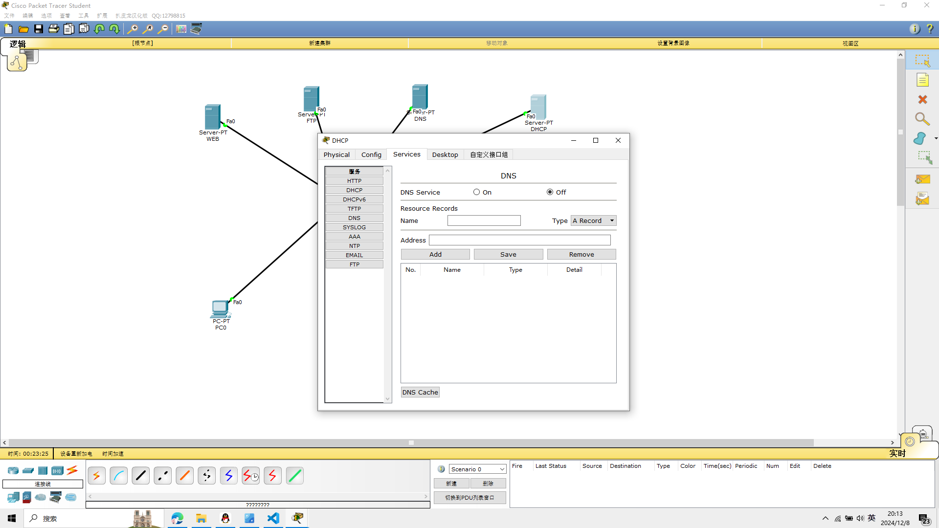
点击左侧DNS,然后Server点击off,其他不变
关闭在此服务器上的DNS、FTP、HTTP
3、WEB配置
将WEB服务器的DNS关闭,FTP关闭,其余不变
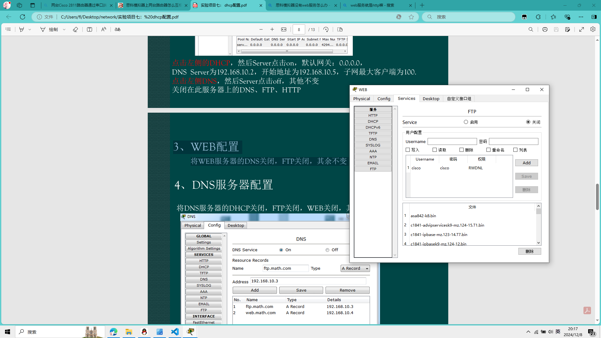
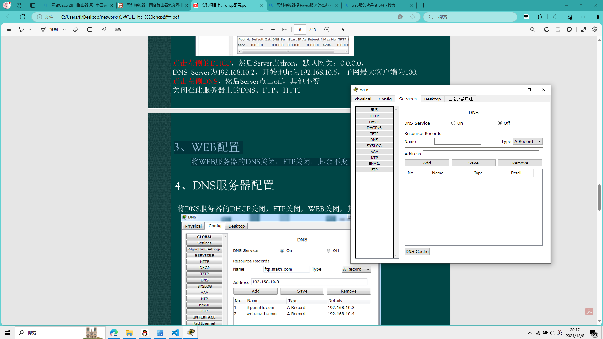
4、DNS服务器配置
将DNS服务器的DHCP关闭,FTP关闭,WEB关闭,其余不变

 增加两条数据

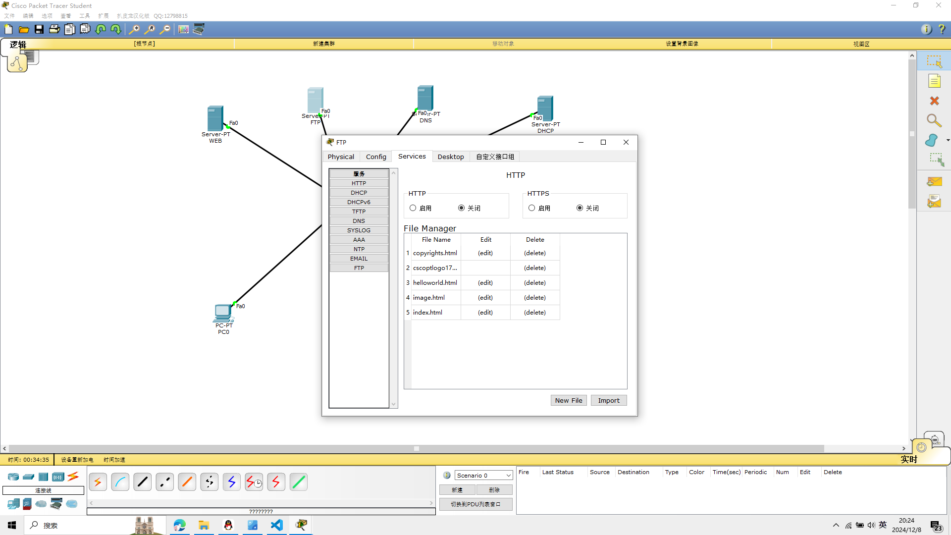
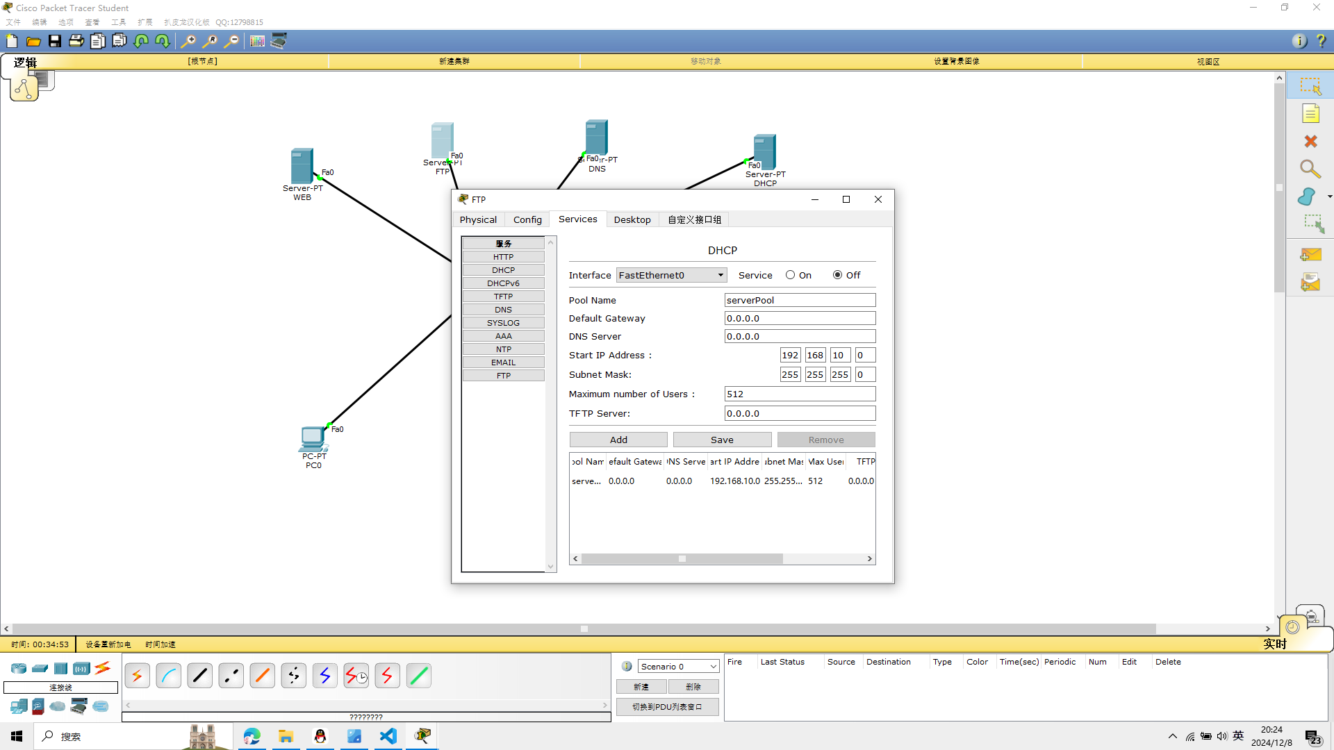
5、FTP服务器配置
将FTP服务器的DHCP关闭,DNS关闭,WEB关闭,其余不变
 设置账号
设置账号
6、计算机IP配置
计算机通过DHCP自动获取IP地址
点击dhcp,自动请求IP
pc0
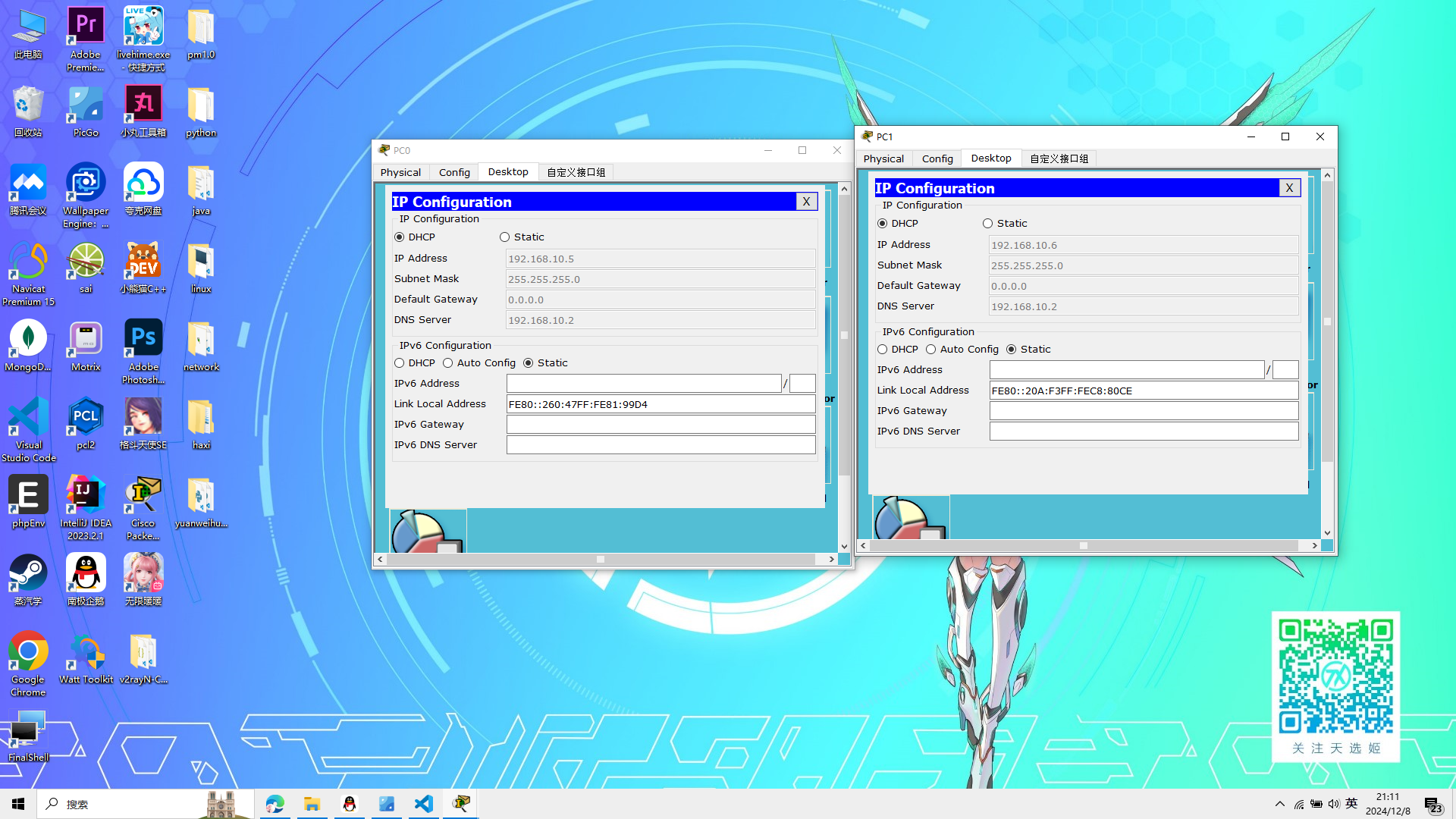 pc1
pc1
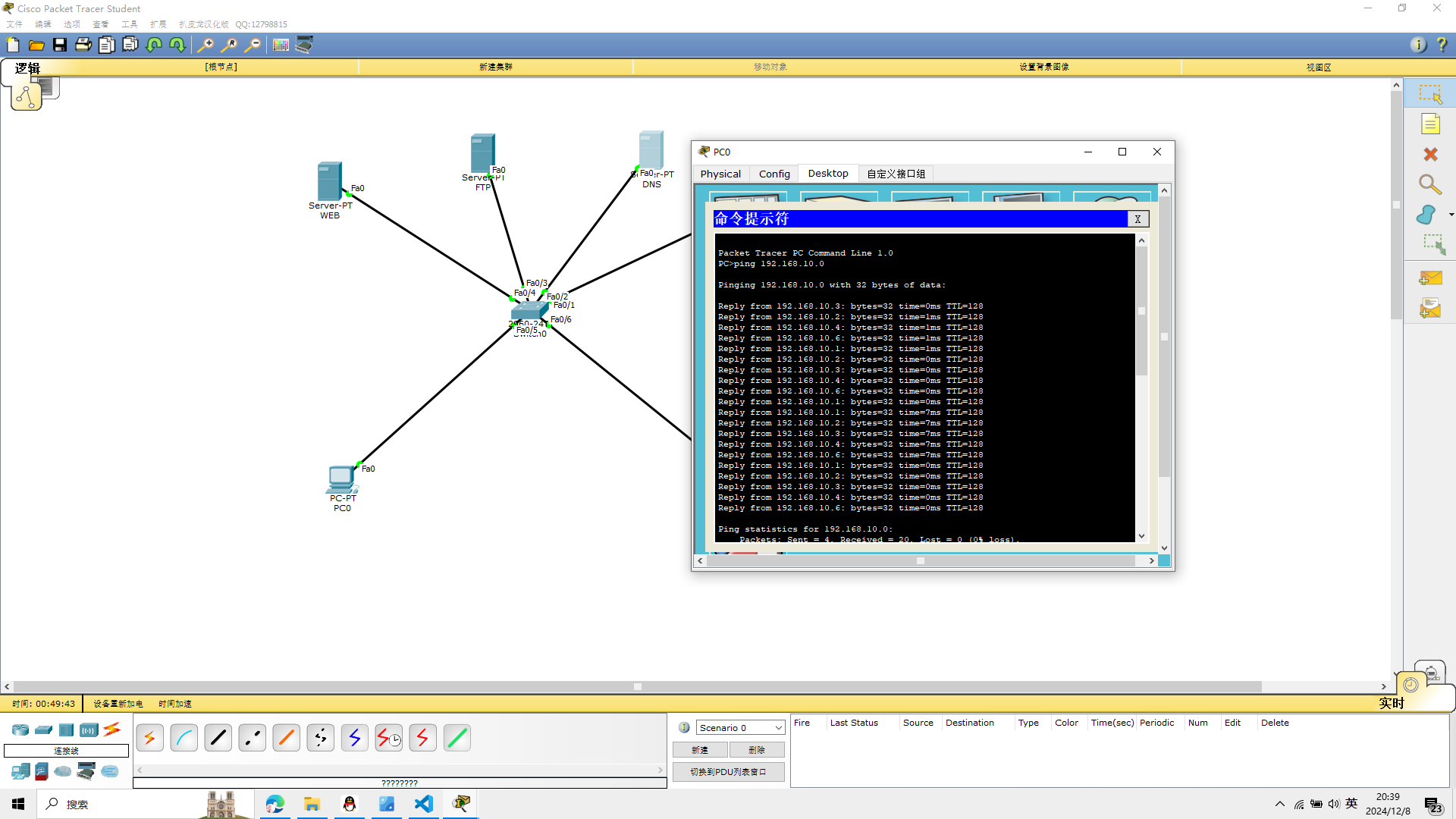
7、计算机与其他设备IP连通性检测
在pc0中,打开终端 ping 192.168.10.0
Pinging 192.168.10.0 with 32 bytes of data:

Reply from 192.168.10.3: bytes=32 time=0ms TTL=128
Reply from 192.168.10.2: bytes=32 time=1ms TTL=128
Reply from 192.168.10.4: bytes=32 time=1ms TTL=128
Reply from 192.168.10.6: bytes=32 time=1ms TTL=128
Reply from 192.168.10.1: bytes=32 time=1ms TTL=128
Reply from 192.168.10.2: bytes=32 time=0ms TTL=128
Reply from 192.168.10.3: bytes=32 time=0ms TTL=128
Reply from 192.168.10.4: bytes=32 time=0ms TTL=128
Reply from 192.168.10.6: bytes=32 time=0ms TTL=128
Reply from 192.168.10.1: bytes=32 time=0ms TTL=128
Reply from 192.168.10.1: bytes=32 time=7ms TTL=128
Reply from 192.168.10.2: bytes=32 time=7ms TTL=128
Reply from 192.168.10.3: bytes=32 time=7ms TTL=128
Reply from 192.168.10.4: bytes=32 time=7ms TTL=128
Reply from 192.168.10.6: bytes=32 time=7ms TTL=128
Reply from 192.168.10.1: bytes=32 time=0ms TTL=128
Reply from 192.168.10.2: bytes=32 time=0ms TTL=128
Reply from 192.168.10.3: bytes=32 time=0ms TTL=128
Reply from 192.168.10.4: bytes=32 time=0ms TTL=128
Reply from 192.168.10.6: bytes=32 time=0ms TTL=128

Ping statistics for 192.168.10.0:
    Packets: Sent = 4, Received = 20, Lost = 0 (0% loss),
Approximate round trip times in milli-seconds:
    Minimum = 0ms, Maximum = 7ms, Average = 1ms

PC>ping 192.168.10.0

Pinging 192.168.10.0 with 32 bytes of data:

Reply from 192.168.10.1: bytes=32 time=0ms TTL=128
Reply from 192.168.10.2: bytes=32 time=0ms TTL=128
Reply from 192.168.10.3: bytes=32 time=0ms TTL=128
Reply from 192.168.10.4: bytes=32 time=0ms TTL=128
Reply from 192.168.10.6: bytes=32 time=0ms TTL=128
Reply from 192.168.10.1: bytes=32 time=0ms TTL=128
Reply from 192.168.10.2: bytes=32 time=0ms TTL=128
Reply from 192.168.10.3: bytes=32 time=0ms TTL=128
Reply from 192.168.10.4: bytes=32 time=0ms TTL=128
Reply from 192.168.10.6: bytes=32 time=0ms TTL=128
Reply from 192.168.10.1: bytes=32 time=0ms TTL=128
Reply from 192.168.10.2: bytes=32 time=0ms TTL=128
Reply from 192.168.10.3: bytes=32 time=0ms TTL=128
Reply from 192.168.10.4: bytes=32 time=0ms TTL=128
Reply from 192.168.10.6: bytes=32 time=0ms TTL=128
Reply from 192.168.10.1: bytes=32 time=0ms TTL=128
Reply from 192.168.10.2: bytes=32 time=1ms TTL=128
Reply from 192.168.10.3: bytes=32 time=0ms TTL=128
Reply from 192.168.10.4: bytes=32 time=1ms TTL=128
Reply from 192.168.10.6: bytes=32 time=0ms TTL=128

Ping statistics for 192.168.10.0:
    Packets: Sent = 4, Received = 20, Lost = 0 (0% loss),
Approximate round trip times in milli-seconds:
    Minimum = 0ms, Maximum = 1ms, Average = 0ms

PC>
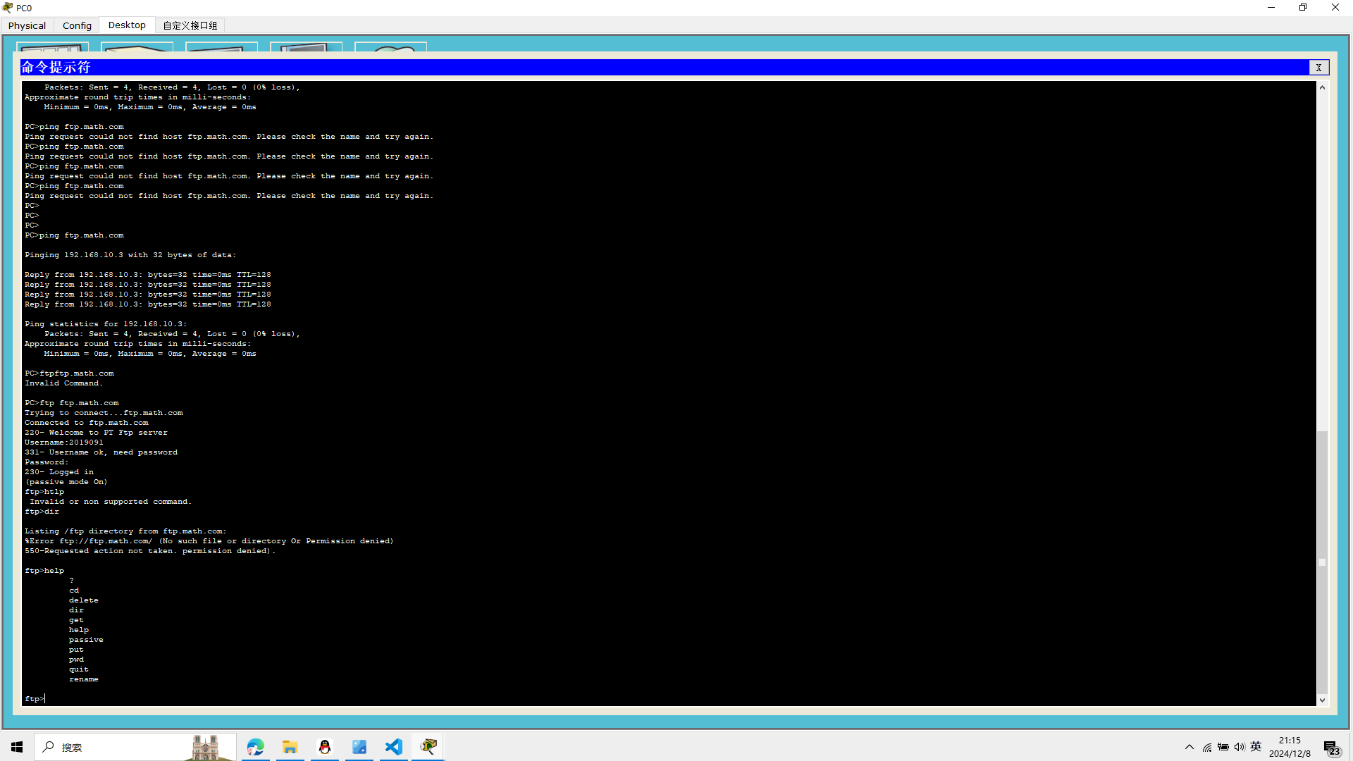
8、登陆FTP服务器
输入help查看操作命令——输入quit退出ftp服务器
ftp ftp.math.com
回车确认
输入账号和密码
PC>ftp ftp.math.com
Trying to connect...ftp.math.com
Connected to ftp.math.com
220- Welcome to PT Ftp server
Username:2019091
331- Username ok, need password
Password:
230- Logged in
(passive mode On)
ftp>htlp
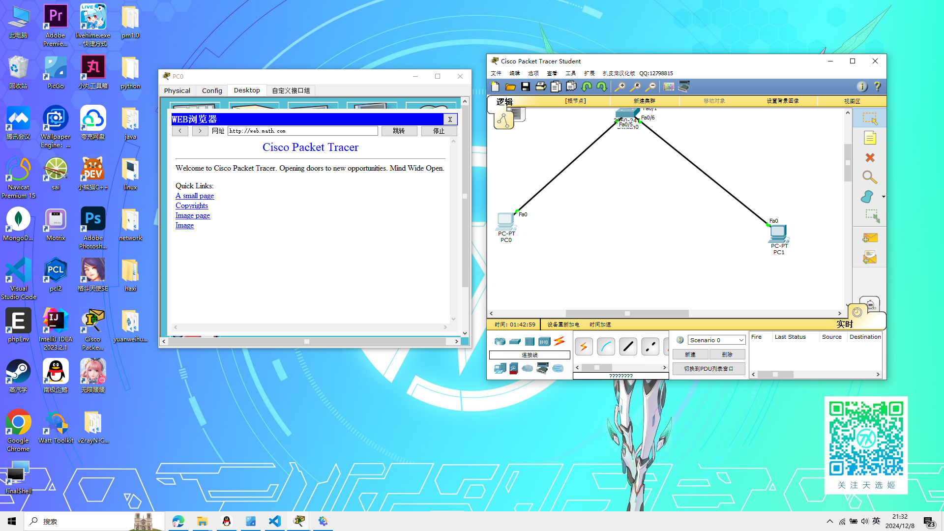
9、客户端访问服务器端
点击计算机——Desktop——Web Browser——输入ftp.math.com,web.math.com
在web浏览器里面输入
web.math.com
思考题
加入MAIL服务器应该怎么设置?
太简单了,不想做
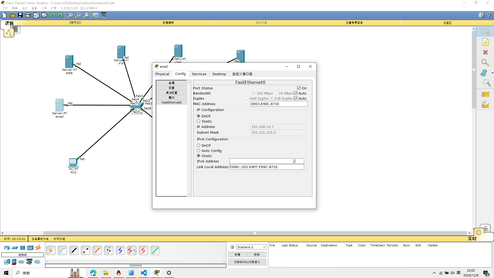
新建一个server取名为email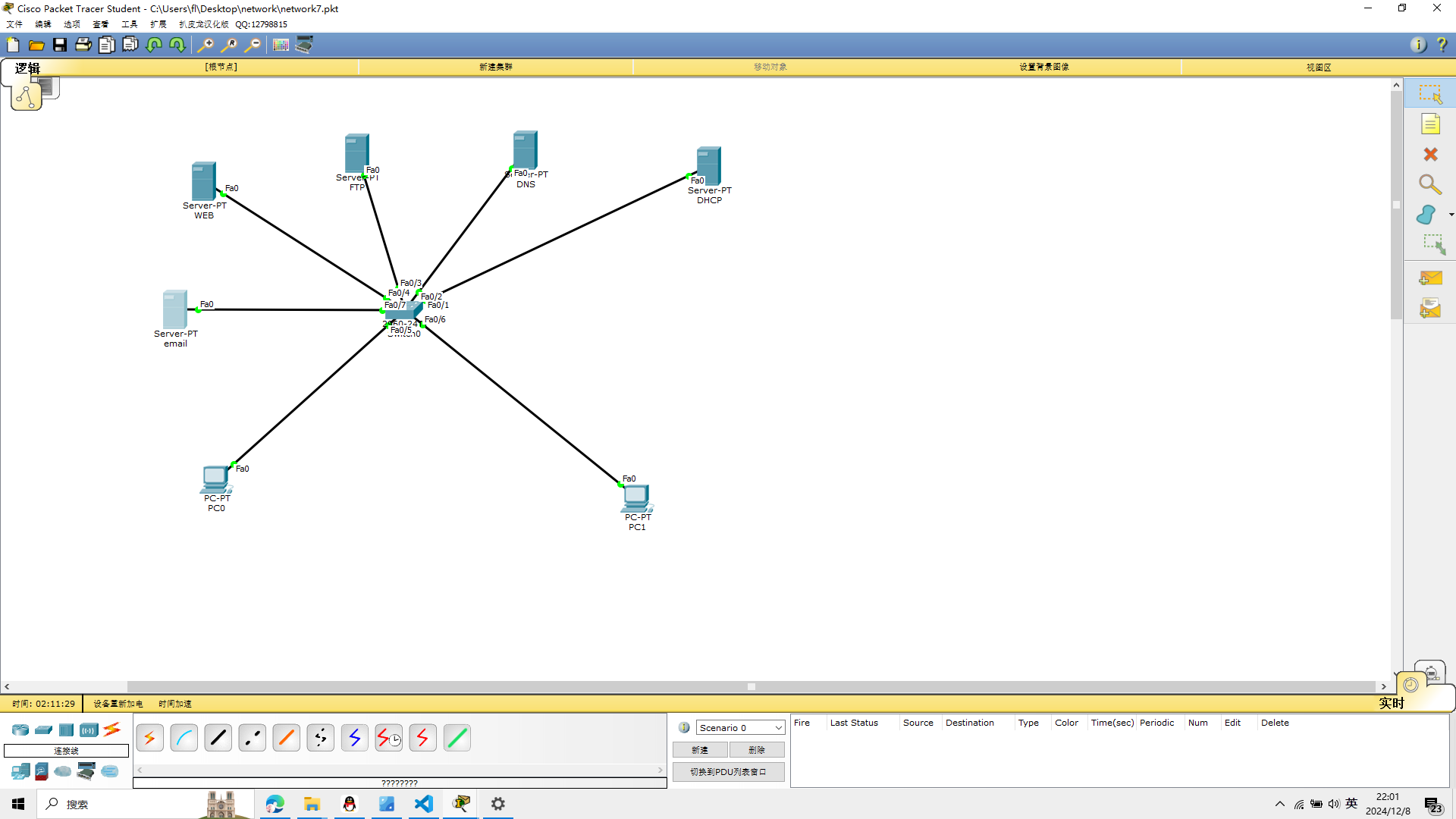 找到接口fastEthernet0
点击dhcp,自动获取IP
 打开服务器的emali,创建2个账号,一个发送,一个接收
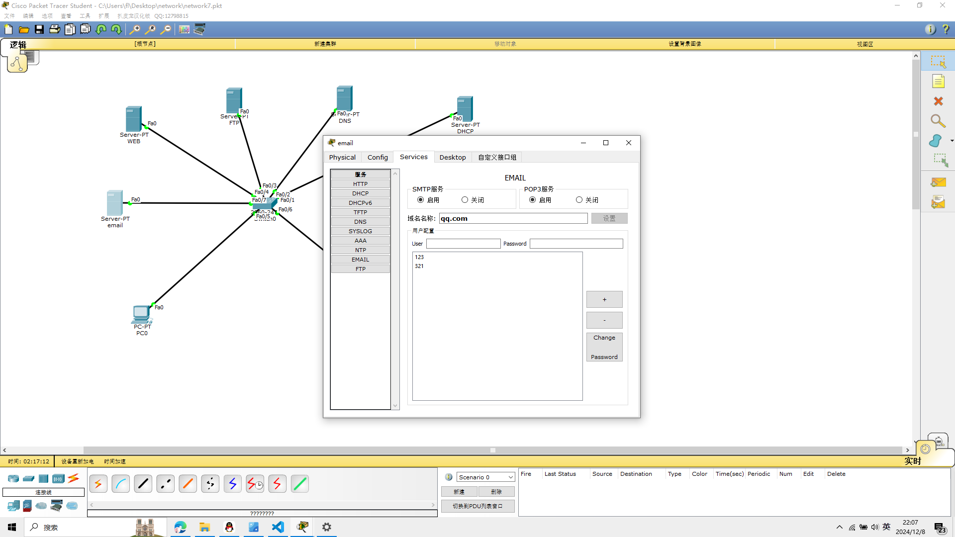 对pc0进行账号设置,参考如图
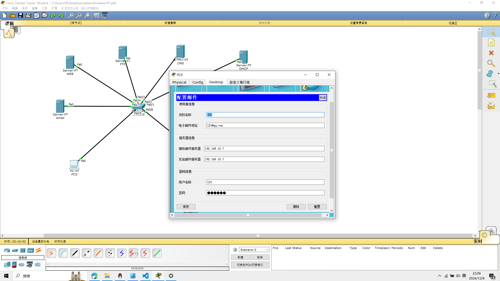 对pc1进行账号设置,参考如图

测试
pc0向pc1发送一封邮件
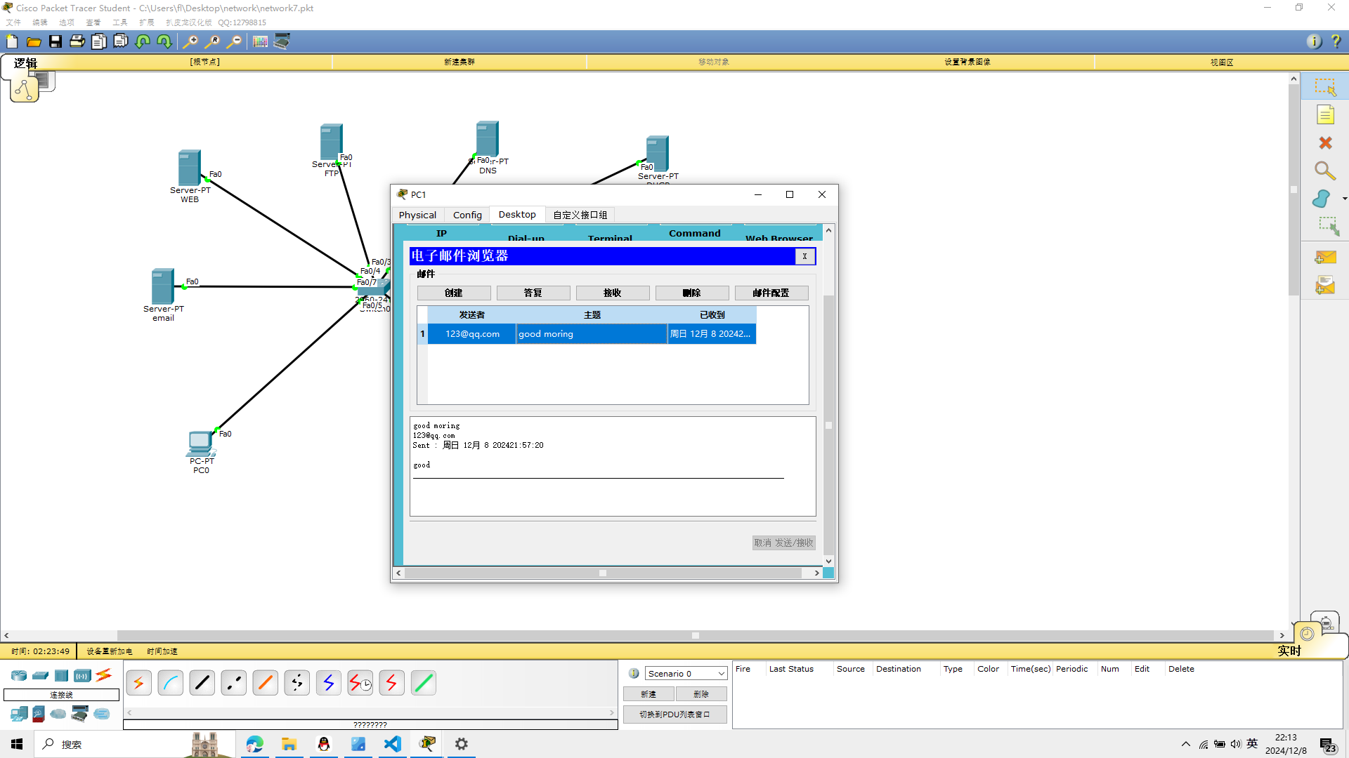 可以看到成功的接受到了邮件
实验7完成
实验八 ACL访问控制配置
实验八的设备
Cisco 3600交换机1台,2960两台
路由器2811一台
PC机2台